
Cars BMW Cars Volkswagen Cars Chevrolet Cars Land Rover Cars Lada Cars Honda Cars Peugeot
English Русский
Български
Беларускі
Український
Српски
Hrvatski
Română
Polski
Slovenský
Magyar
Bookmark News and articles Sitemap Feedback Site search
MercedesMan.ru


A-Class C-Class E-Class G-Class M-Class S-Class Others
W123 (1976-1985) W124 (1984-1995) W210 (1996-2002)
  • Main
  • E-Class
  • W123 (1976-1985)
  • Electrical equipment
  • Electrical circuits
  • Electrical diagram of the model «280TE» with engine 123.093, starting with chassis No. 007 619

Electrical diagram of the model «280TE» with engine 123.093, starting with chassis No. 007 619 (Mercedes-Benz E-Class W123)

0
Contents: Legend of the basic electrical…↡ Connection points with the "mass" ↡ Schematic diagram of electrical…↡ Schematic diagram of electrical…↡

Legend of the basic electrical circuit diagram of electrical equipment


№

Designation

1

Left headlight:

a

  • high beam thread

b

  • low beam thread

with

  • side/parking light lamp

e

  • turn signal lamp

2

Brake Fluid Level Warning Light Sensor

3

Left front brake lining wear sensor

4

Right front brake lining wear sensor

5

Instrument cluster:

a

  • left turn signal indicator light

b

  • high beam indicator lamp

with

  • coolant temperature gauge

d

  • fuel gauge

e

  • fuel reserve indicator light

f

  • low battery indicator light

g

  • brake lining wear indicator light

h

  • brake fluid level and parking brake warning light

i

  • instrument lighting lamps

j

  • instrument lighting rheostat

k

  • emergency sound signaling device

l

  • right turn signal indicator lamp

m

  • electronic clock

6

Cigarette lighter with ashtray lamp

7

Radio

8

Right headlight:

a

  • high beam thread

b

  • low beam thread

with

  • side/parking light lamp

d

  • fog light lamp

e

  • turn signal lamp

9

Fuel injection start mode switch

10

Starting fuel valve

11

Automatic antenna*

12

Parking brake indicator light switch

13

Coolant Temperature Gauge Sensor

14

Contact for switching on the emergency sound signaling device

15

Front ceiling light with switch

16

Ceiling light switch in the left front door pillar

17

Ceiling light switch in the right front door pillar

18

Two-tone sound signal (fanfare)

19

Speed controller sensor*

20

Speed controller amplifier*

21

Actuator of the software speed controller*

22

Electronic alarm switch/relay

23

Glove compartment light switch

24

Glove compartment light

25

Fuse box

26

Engine warm-up heating element

27

Fuel pump relay with electronic engine warm-up speed limiter

28

Air conditioning compressor electromagnetic clutch*

29

Relay I for switching on window lifters*

30

Relay II for switching on window lifters*

31

Door window switch*

32

Speed control software switch*:

A

  • off

V

  • slowdown/tuning

SP

  • return to previous speed of movement

IN

  • overclocking/tuning

33

Combined steering column switch:

a

  • turn signal switch

b

  • headlight signal switch

with

  • headlight switch

e

  • windshield wiper speed switch

I

  • intermittent operation

II

  • low speed

III

  • high speed

34

Horn switch

35

Windshield wiper motor

36

Windscreen wiper intermittent relay

37

Ignition switch

38

Light switch

39

Sunroof Electric Motor*

40

Electric sunroof switch*

41

Automatic Transmission Solenoid Valve*

42

Foot switch for low gear engagement*

43

Starter interlock and reversing light switch*

44

Air Conditioning Compressor Emergency Pressure Sensor* (switching on at 2.6 kgf/cm², switching off at 2.0 kgf/cm²)

45

Air Conditioner Relay II*

46

Fan switch with light

47

Brake light switch

48

Windshield washer pump

49

Left headlight wiper motor*

50

Right headlight wiper motor*

51

Headlight Washer Relay*

52

Headlight washer pump*

53

Transistor ignition switch

54

Contactless ignition distributor

55

Spark plugs

56

Ignition coil

57

Lighting:

a

  • air flow direction knobs

b

  • heater control knobs

with

  • switch*

58

Throttle lift control system changeover valve

59

Thermoelectric switch (52°C) of the air conditioner dryer*

60

Thermoelectric switch (100°C)

61

Additional fan*

62

Additional fan relay*

63

Changeover valve for outside or recirculated air*

64

Air conditioner temperature sensor*

65

Air conditioner temperature selection switch*

66

Additional resistance of the fan motor

67

Fan motor

68

Additional resistance 0.6 Ohm

69

Left rear door window lift motor*

70

Left rear door window switch*

71

Power window switch block*:

a

  • left rear door window switch

b

  • safety switch

with

  • left front door window switch

d

  • right front door window switch

e

  • right rear door window switch

72

Left front door window lift motor*

73

Additional resistance 0.4 Ohm

74

Rear window heating time relay*

75

Rear window defroster switch*

76

Gear shift lever illumination*

77

Starter

78

Battery

79

Generator with electronic voltage regulator

80

Intermittent relay for rear window wiper

81

Rear door glass wiper motor

82

Fuel level indicator sensor

83

Fuel pump

84

Tail Light Wiring Harness Connector

85

Tailgate wiper motor lock switch or tailgate wiper intermittent switch

86

TDC sensor

87

Right front door window lift motor*

88

Diagnostic connector

89

Right rear door window switch*

90

Right rear door window lift motor*

91

Rear lamp with switch

92

Left rear light:

a

  • turn signal lamp

b

  • red/parking light lamp

with

  • brake light bulb

93

Rear fog light

94

Rear door glass washer pump

95

Rear courtesy light lock switch or rear window washer pump pushbutton switch

96

License plate light

97

Rear window heating element*

98

Ceiling light switch in left rear door pillar*

99

Ceiling light switch in the right rear door pillar*

100

Switch in the tailgate

101

Ground connection point for tailgate wiring

102

Reverse light lamp

103

Right rear light:

a

  • turn signal lamp

b

  • red/parking light lamp

with

  • brake light bulb

* Depending on the configuration.


Connection points with the "mass"


№

Designation

M1

main connection point with the "mass" (behind the instrument cluster)

M2

front-right connection point with the "mass" (near the headlight)

M3

ground connection point on the left front wheel mudguard (for ignition coil)

M4

ground connection point of the front interior light

M5

"mass" of the engine

M6

ground connection point in the luggage compartment on the left wing mudguard

M7

ground connection point in the luggage compartment on the right wing mudguard

M8

ground connection point on the tailgate


Schematic diagram of electrical equipment (1)
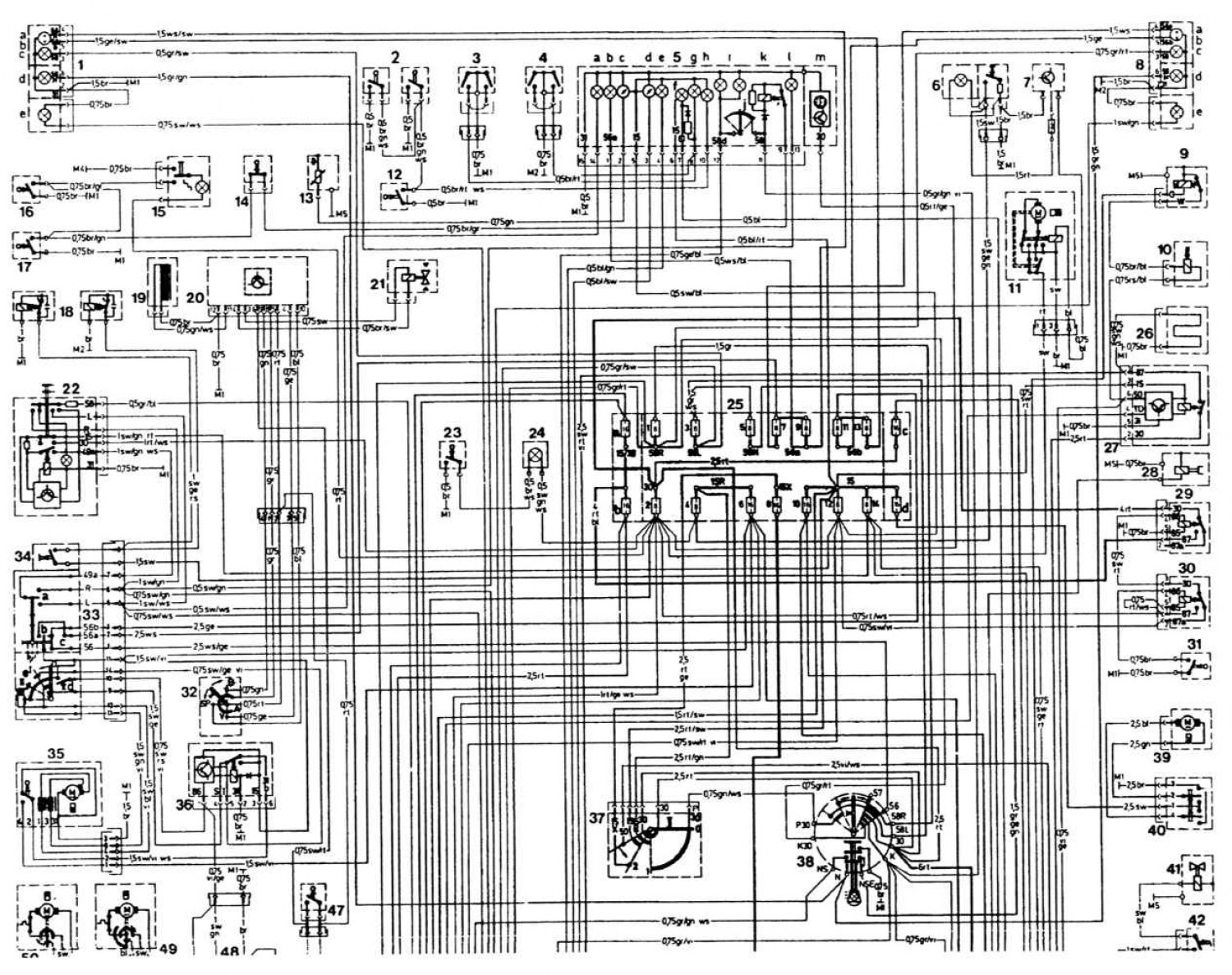


Open a larger image in a new tab »

Schematic diagram of electrical equipment (2)
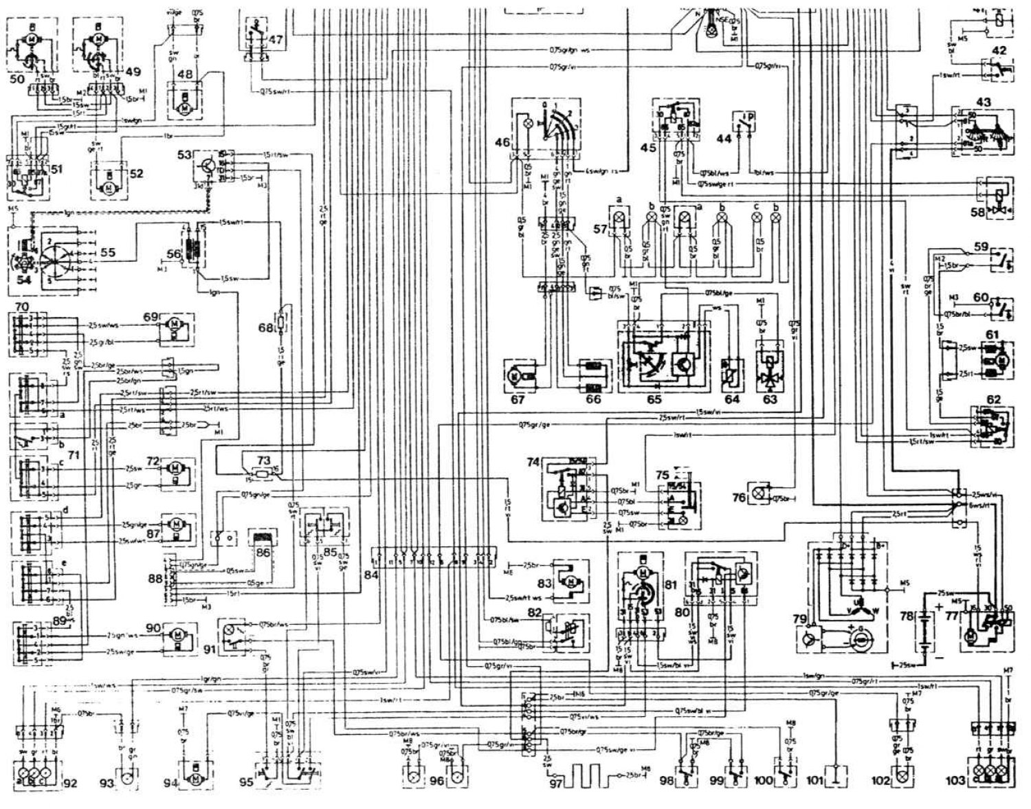


Open a larger image in a new tab »
This article is available at: russian, bulgarian, belarusian, ukrainian, serbian, croatian, romanian, polish, slovak, hungarian
The article has been verified: Levin Kirill Glebovich
Share with friends:
◀ Previous
E-Class W123 / Electrical circuits
Next ▶

Electrical diagram of the model «280TE» with engine 123.093
Electrical diagram of the model «280E» (engine 123.033) and «280CE» (engine 123.053)
Electrical diagram of the model «280E» with engine 123.033
Electrical diagram of the model «250» with engine 123.026
Models «280» with engine 123.030
More similar articles for repairing other models

☛ Starting the engine using an auxiliary battery Mercedes W168 (1997-2004)
☛ Electrical diagram of the starting system Mercedes W203 (2000-2007)
☛ Starting the engine from an auxiliary power source Mercedes W463 (1999-2019)
☛ Starting the engine from an auxiliary power source Mercedes W163 (1997-2005)
☛ Electrical diagram of a 6-cylinder carburetor engine Mercedes W126 (1979-1991, petrol)
☛ Scheme 6. Electrical supply and starting systems of engine 601.943… Mercedes Sprinter (1995-2000, diesel)
Link in different formats to this article
Comments and feedback from visitors
No comments yet


How much will 39 + 15 ?


W210 (1996-2002) 
  • General information
  • Vehicle description
  • Working conditions and tools
  • Car care
  • Diesel engines
  • Engine repair
  • Lubrication system
  • Cooling system
  • Injection system
  • Supply system
  • Exhaust system
  • Gasoline engines
  • Engine repair
  • Lubrication system
  • Cooling system
  • Control system
  • Power and exhaust system
  • Transmission
  • Clutch
  • Mechanical gearbox
  • Automatic gearbox
  • Drive shafts
  • Chassis
  • Car suspension
  • Steering
  • Tires and wheels
  • Brake system
  • Body
  • Exterior (external elements)
  • Interior (internal elements)
  • Doors and windows
  • Heating and ventilation
  • Electrical equipment
  • Equipment and devices
  • Power devices
  • Lighting and signaling
  • Electrical circuits
W124 (1984-1995) 
  • General information
  • Governing bodies
  • Driving and operation
  • Weekly care
  • Maintenance (gasoline)
  • Maintenance (diesel)
  • Troubleshooting
  • Power unit
  • I4 petrol engine
  • V6 petrol engine (SOHC)
  • V6 petrol engine (DOHC)
  • Diesel engines
  • Engine overhaul
  • Cooling system
  • Heating and ventilation
  • Fuel system (carburetor)
  • Injection system «Bosch CIS-E»
  • Injection system «Bosch HFM»
  • Diesel fuel system
  • Supply system
  • Starting and charging system
  • Ignition system (I4)
  • Ignition system (V6)
  • Preheating
  • Transmission
  • Clutch
  • Mechanical gearbox
  • Automatic gearbox
  • Drive shafts
  • Chassis
  • Brake system
  • Car suspension
  • Steering
  • Body
  • Exterior (external elements)
  • Interior (internal elements)
  • Doors, locks and windows
  • Electrical equipment
  • Equipment and devices
  • Switches
  • Headlights and lighting
  • Electrical circuits
W123 (1976-1985) 
  • General information
  • Introduction to the guide
  • Power unit
  • Engine device
  • Repair M102 engines
  • Repair M110 and M123 engines
  • Cooling and lubrication (M102)
  • Cooling (M110 and M123)
  • Ignition system
  • Power system «Stromberg»
  • Power system «Solex 4A1»
  • Fuel injection «K-Jetronic»
  • Fuel injection «L-Jetronic»
  • Transmission
  • Clutch
  • Mechanical gearbox
  • Automatic gearbox
  • Cardan and rear axle
  • Chassis
  • Front suspension
  • Rear suspension
  • Steering
  • Brake system
  • Body
  • Exterior (external elements)
  • Interior (internal elements)
  • Doors, locks and windows
  • Electrical equipment
  • Equipment and devices
  • Power devices
  • Electrical circuits
 
MercedesMan.ru © 2017–2026 · Mobile version · Read about Mercedes · Sitemap: EN BG BY UA RS HR RO PL SK HU · Feedback · Site search · Bookmark A-Class (W168) · C-Class (W201) · C-Class (W202) · C-Class (W203) · E-Class (W123) · E-Class (W124) · E-Class (W210) · G-Class (W463) · M-Class (W163) · S-Class (W116, petrol) · S-Class (W126, petrol) · S-Class (W140) · S-Class (W220) · Sprinter · Vito 1 · Vito 2 · Vario 814D ·
 
We only use cookies without which some of the site's features may not be available.