



Legend of the basic electrical circuit diagram of electrical equipment
№ | Designation |
| 1 | Left headlight: |
| a |
|
| b |
|
| with |
|
| d |
|
| e |
|
| 2 | Brake Fluid Level Warning Light Sensor |
| 3 | Left front brake lining wear sensor |
| 4 | Gear Shift Lever Illumination Lamp* |
| 5 | Instrument cluster: |
| a |
|
| b |
|
| with |
|
| d |
|
| e |
|
| f |
|
| g |
|
| h |
|
| i |
|
| j |
|
| k |
|
| l |
|
| 6 | Cigarette lighter with ashtray lamp |
| 7 | Radio* |
| 8 | Right headlight: |
| a |
|
| b |
|
| with |
|
| d |
|
| e |
|
| 9 | Automatic air damper heating coil |
| 10 | Idle Fuel Shut-Off Solenoid Valve II |
| 11 | Automatic antenna* |
| 12 | Parking brake indicator light switch |
| 13 | Coolant temperature sensor |
| 14 | Right front brake lining wear sensor |
| 15 | Front ceiling light with switch |
| 16 | Ceiling light switch in the left door pillar |
| 17 | Ceiling light switch in the right door pillar |
| 18 | Sound signal |
| 19 | Speed controller sensor* |
| 20 | Speed controller amplifier* |
| 21 | Throttle actuator* |
| 22 | 4-way alarm switch/relay interrupter |
| 23 | Glove box light switch |
| 24 | Glove compartment light |
| 25 | Fuse box |
| 26 | Idle Fuel Shut-Off Solenoid Valve I |
| 27 | Relay I for switching on window lifters* |
| 28 | Relay II for switching on window lifters* |
| 29 | Door window switch* |
| 30 | Horn switch |
| 31 | Combined steering column switch: |
| a |
|
| b |
|
| with |
|
| d |
|
| e |
|
| I |
|
| II |
|
| III |
|
| 32 | Speed control software switch: |
| A |
|
| V |
|
| SP |
|
| IN |
|
| 33 | Windshield wiper motor |
| 34 | Windscreen wiper intermittent relay |
| 35 | Ignition switch |
| 36 | Rotary light switch |
| 37 | Sunroof Electric Motor* |
| 38 | Electric sunroof switch* |
| 39 | Automatic Transmission Solenoid Valve* |
| 40 | Foot switch for low gear engagement* |
| 41 | Starter interlock and reversing light switch* |
| 42 | Air Conditioner Relay II* |
| 43 | Air Conditioner Relay I* |
| 44 | Fan switch with light |
| 45 | Brake light switch |
| 46 | Windshield washer pump |
| 47 | Left headlight wiper motor* |
| 48 | Right headlight wiper motor* |
| 49 | Headlight Washer Relay* |
| 50 | Headlight washer pump* |
| 51 | Distributor* |
| 52 | Spark plugs |
| 53 | Ignition coil |
| 54 | Lighting: |
| a |
|
| b |
|
| with |
|
| 55 | Thermoelectric switch (62°C) of the air conditioner dryer* |
| 56 | Thermoelectric switch (100°C) |
| 57 | Left rear door window lift motor* |
| 58 | Left rear door window switch* |
| 59 | Power window switch block*: |
| a |
|
| b |
|
| with |
|
| d |
|
| e |
|
| 60 | Fan motor |
| 61 | Additional resistance of the fan motor |
| 62 | Air conditioning temperature selector switch with lighting* |
| 63a | Air conditioning compressor electromagnetic clutch* |
| 63b | Air Conditioning Compressor Emergency Pressure Sensor* (switching on at 2.6 kgf/cm², switching off at 2.0 kgf/cm²) |
| 64 | Additional fan* |
| 65 | Additional fan relay* |
| 66 | Rear window defroster switch |
| 67 | Rear window heating time relay |
| 68 | Additional resistance 1.8 Ohm |
| 69 | Left front door window lift motor* |
| 70 | Right front door window lift motor* |
| 71 | Diagnostic connector |
| 72 | TDC sensor |
| 73 | Luggage compartment light |
| 74 | Wiring connector to rear vehicle consumers |
| 75 | Right rear door window switch* |
| 76 | Right rear door window lift motor* |
| 77 | Fuel level indicator sensor |
| 78 | Rear interior light |
| 79 | Ceiling light switch in left rear door pillar* |
| 80 | Rear Interior Light Switch* |
| 81 | Ceiling light switch in the right rear door pillar* |
| 82 | Generator with electronic voltage regulator |
| 83 | Battery |
| 84 | Starter |
| 85 | Right rear light: |
| a |
|
| b |
|
| with |
|
| d |
|
| 86 | Rear window heating element* |
| 87 | License plate light |
| 88 | Left rear light: |
| a |
|
| b |
|
| with |
|
| d |
|
| e |
|
* Depending on the configuration.
Wire color designation
Designation | Transcript |
bl | blue |
br | brown |
el | ivory |
ge | yellow |
gn | green |
gr | grey |
nf | colorless |
rs | pink |
rt | red |
sw | black |
vi | violet |
ws | white |
The first two letters indicate the color of the wire, the second two letters indicate the color of the stripe on the wire. The numbers next to the color designation of the wire indicate its cross-section in mm².
Schematic diagram of electrical equipment (1)
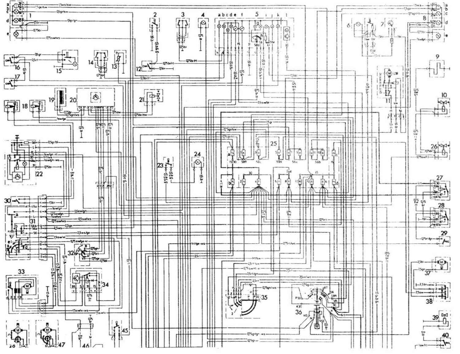
Open a larger image in a new tab »
Schematic diagram of electrical equipment (2)
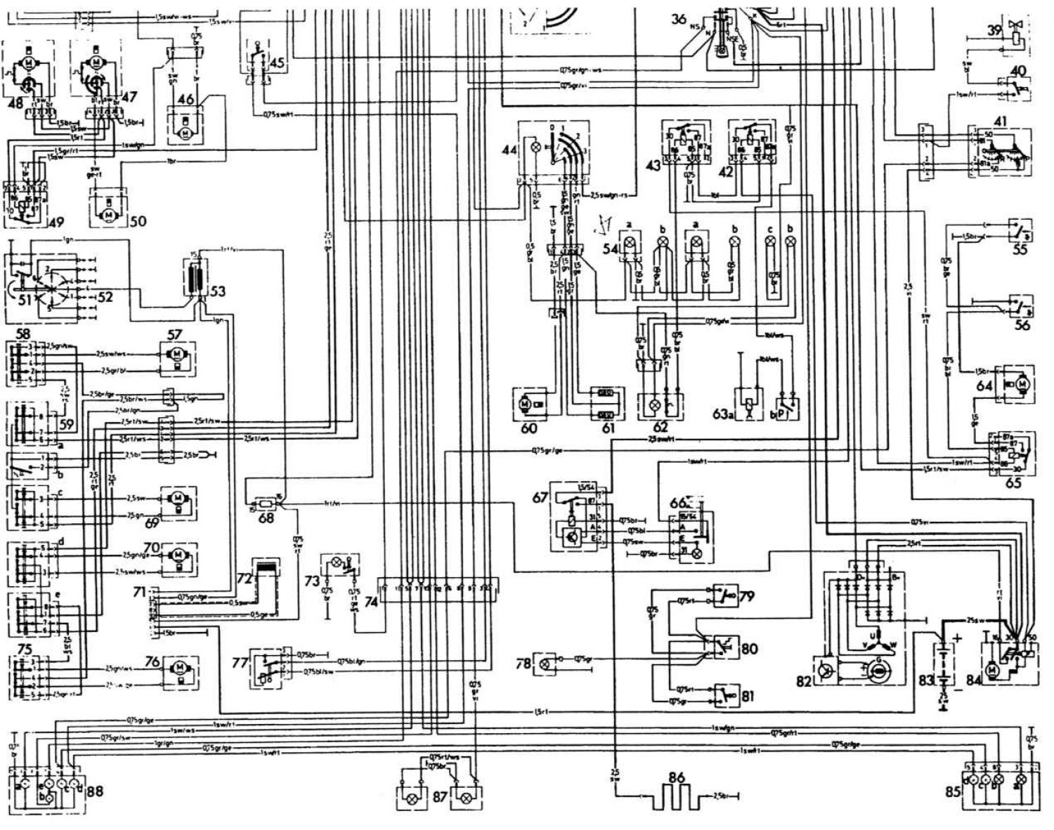
Open a larger image in a new tab »
(Original can be found on the website: MercedesMAN)