
Disassembly
Disassembly and assembly of clutch K1
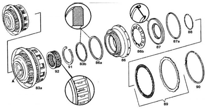
83a - Outer clutch support K1; 83b - O-ring; 86 - Piston; 86a - Piston O-ring; 86b - Disc spring; 87 - Spring plate; 87a - O-ring spring plate; 88, 90 - Retaining rings; 89 - Disc block; 91 - Retaining ring of the freewheel; 92 - Front freewheel; A - Oil channel for K1 clutch
1. Remove retaining ring (90) from an external support.
2. Remove the drive unit (89) from an external support.
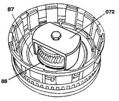
3. Install the puller (072) on the spring plate (87) and squeeze it until the retaining ring (88) will not be released.
4. Remove disc spring (86b) and piston (86), feeding into the hole (A) compressed air.
Assembly
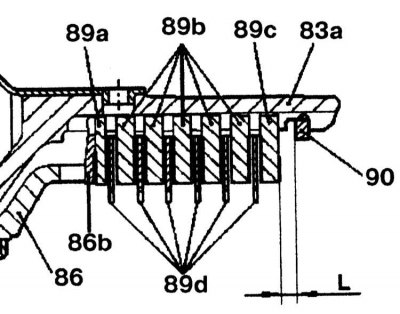
Checking the gap between the circlip (90) and outer disc (89c)
83a - Outer clutch support K1; 86 - Piston; 86b - Disc spring; 89a - Outer disc (1.8 mm thick); 89b - Outer disc (thickness 3.5mm/new thickness 2.8mm); 89c - Outer disc (4.0 mm thick); 89d - Friction discs; 90 - Retaining ring; L - Gap
Assembly is carried out in the reverse order of disassembly. Check clearance between retaining ring (90) and outer disc (89c). The size of the gaps in the clutch K1 is shown in the table below. If necessary, adjust the gap by selecting the retaining ring (90) required thickness. Rings are available in thicknesses of 2.6, 2.9, 3.2, 3.5, 3.8 and 4.1 mm.
The size of the gaps in the clutch K1
| Disk | Gap size, mm |
3 | 2.70-3.10 |
4 | 3.00-3.40 |
5 | 3.30-3.70 |