



Contents: Basic information ↡ Advantages ↡ Data packet format ↡ Priorities ↡ Example ↡ Error recognition ↡ Data Frame Level Mechanisms ↡ Bit-level mechanisms ↡ Troubleshooting ↡ CAN bus types ↡ CAN C - "Engine and chassis" bus ↡ CAN B - "Salon" bus ↡
Data exchange via CAN bus
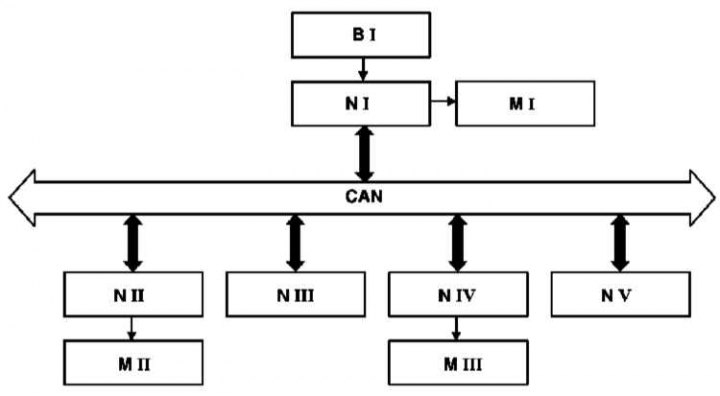
B - Sensor 1; CAN - Data Bus; M - Executive elements I - III (servomechanisms); N - Control units (controllers) I-V
Basic information
The vehicle uses several CAN data exchange network buses (Controller Area Network) between control units (modules) of various systems and controllers of vehicle actuators.
Individual control units are connected to each other in a common network and can exchange data.
The bus is bidirectional, meaning that any device connected to it can receive and transmit messages.
The signal from the sensitive element (sensor) is sent to the nearest control unit, which processes it and transmits it to the CAN data bus.
Any control unit connected to the CAN data bus can read this signal, calculate the control action value based on it and control the actuator servo.
Advantages
With a conventional cable connection of electrical and electronic devices, a direct connection is made between each control unit and all sensors and actuators from which it receives measurement results or which it controls.
The complication of the control system leads to excessive length or number of cable lines.
Compared to standard cabling, the data bus provides:
- Reduction in the number of cables. The wires from the sensors are only drawn to the nearest control unit, which converts the measured values into a data packet and transmits it to the CAN bus.
- The actuator can be controlled by any control unit that receives the corresponding data packet via the CAN bus and, based on it, calculates the value of the control action on the servomechanism.
- Improving electromagnetic compatibility.
- Reduction in the number of plug connections and reduction in the number of contact terminals on control units.
- Weight loss.
- Reducing the number of sensors, since the signals from one sensor (for example, from the coolant temperature sensor) can be used by different systems.
- Improved diagnostic capabilities. Since signals from one sensor (for example, speed signal) are used by different systems, then if a fault message is issued by all systems using this signal, the fault is usually in the sensor or control unit that processes its signals. If a fault message is received from only one system, although this signal is also used by other systems, then the cause of the fault is most often in the processing control unit or servo mechanism.
- High data transfer rate - up to 1 Mbit/s is possible with a maximum line length of 40 m. Currently, the data transfer rate on Mercedes-Benz vehicles ranges from 83 Kbit/s to 500 Kbit/s.
- Several messages can be transmitted successively over the same line.
The CAN data bus consists of a two-wire cable made in the form of a twisted pair. All devices are connected to this line (device control units).
Data transmission is carried out with duplication on both wires, and the logical levels of the data bus are mirrored (that is, if a logical zero level (0) is transmitted on one wire, then a logical one level (1) is transmitted on the other wire, and vice versa).
The two-wire transmission scheme is used for two reasons: to detect errors and as a basis for reliability.
If a voltage peak occurs on only one wire (for example, due to EMC problems (electromagnetic compatibility)), then the receiving units can identify this as an error and ignore this voltage peak.
If a short circuit or break occurs in one of the two CAN data bus wires, then thanks to the integrated software and hardware reliability system, switching to single-wire operation mode will occur. The damaged transmission line will not be used.
The order and format of data transmitted and received by users (subscribers) messages are defined in the data exchange protocol.
An essential distinguishing feature of the CAN data bus compared to other bus systems based on the subscriber addressing principle is message-related addressing.
This means that each message on the CAN data bus is assigned its own permanent address (identifier), marking the content of this message (eg: coolant temperature). The CAN data bus protocol allows the transmission of up to 2048 different messages, with addresses from 2033 to 2048 being permanently assigned.
The data volume in one message on the CAN data bus is 8 bytes.
The receiver block processes only those messages (data packets), which are stored in its list of received CAN messages via the data bus (acceptability control).
Data packets can only be transmitted if the CAN data bus is free (i.e., if after the last data packet there followed a 3-bit interval, and none of the control units starts transmitting a message).
In this case, the logical level of the data bus must be recessive (logical "1").
If several control units start transmitting messages at the same time, the priority principle comes into effect, according to which the CAN data bus message with the highest priority will be transmitted first without loss of time or bits (arbitration of requests for access to the shared data bus).
Each control unit that loses its arbitration right automatically switches to receive and tries to send its message again as soon as the CAN data bus is free again.
In addition to data packets, there is also a request packet for a specific message on the CAN data bus.
In this case, the control unit that can provide the requested data packet responds to this request.
Data packet format
In normal transmission mode, data packets have the following block configurations (frames):
- Data Frame (message frame) for transmitting messages via the CAN data bus (eg: coolant temperature).
- Remote Frame (request frame) to request messages via the CAN data bus from another control unit.
- Error Frame (error frame) all connected control units are notified that an error has occurred and the last message on the CAN data bus is invalid.
The CAN data bus protocol supports two different CAN data bus message frame formats, which differ only in the length of the identifier:
- standard format;
- extended format.
DaimlerChrysler currently uses only the standard format.
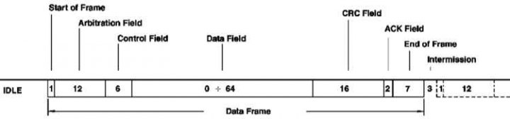
The data packet for transmitting messages via the CAN data bus consists of seven consecutive fields:
- Start of Frame (start bit): Marks the start of a message and synchronizes all modules.
- Arbitration Field (identifier and request): This field consists of an 11-bit identifier (address) and 1 control bit (Remote Transmission Request-Bit). This control bit marks the packet as a Data Frame (message frame) or as Remote Frame (request frame) without data bytes.
- Control Field (control bits): The control field (6 bits) contains the IDE bit (Identifier Extension Bit) to recognize the standard and extended format, a reserve bit for subsequent extensions and - in the last 4 bits - the number of bytes of data contained in the Data Field (data field).
- Data Field: The data field can contain 0 to 8 bytes of data. A 0-byte CAN data bus message is used to synchronize distributed processes.
- CRC Field (control field): CRC field (Cyclic-Redundancy-Check Field) contains 16 bits and is used for control recognition of errors during transmission.
- ACK Field (confirmation of acceptance): ACK field (Acknowledgement Field) contains a signal confirming the receipt of all receiver units that have received a message via the CAN bus without errors.
- End of Frame (end of frame): Marks the end of a data packet.
- Intermission: The interval between two data packets. The interval must be at least 3 bits. After this, any control unit can transmit the next data packet.
- IDLE (rest mode): If no control unit transmits messages, the CAN bus remains in idle mode until the next data packet is transmitted.
Priorities
To process data in real time, it must be possible to transmit it quickly.
This not only requires a high physical data rate line, but also requires rapid access to the common CAN bus if multiple control units need to transmit messages simultaneously.
In order to differentiate the messages transmitted via the CAN data bus according to their degree of urgency, different priorities are provided for individual messages.
The ignition timing, for example, has the highest priority, the slip values have the average priority, and the outside air temperature has the lowest priority.
The priority with which a message is transmitted over the CAN bus is determined by the identifier (address) of the corresponding message.
The identifier corresponding to the smaller binary number has higher priority, and vice versa.
The CAN data bus protocol is based on two logical states: Bits are either "recessive" (logical "1") or "dominant" (logical "0"). If a dominant bit is transmitted by at least one module, then recessive bits transmitted by other modules are overwritten.
Example
If several control units simultaneously start transmitting data, the conflict for access to the common data bus is resolved by "bitwise arbitration of common resource requests" using the corresponding identifiers.
When transmitting the identifier field, the transmitter unit checks after each bit whether it still has the right to transmit, or whether another control unit is already transmitting a message with a higher priority via the CAN data bus.
If the recessive bit transmitted by the first transmitter block is overwritten by the dominant bit of another transmitter block, then the first transmitter block loses its right to transmit (arbitration) and becomes the receiving block.
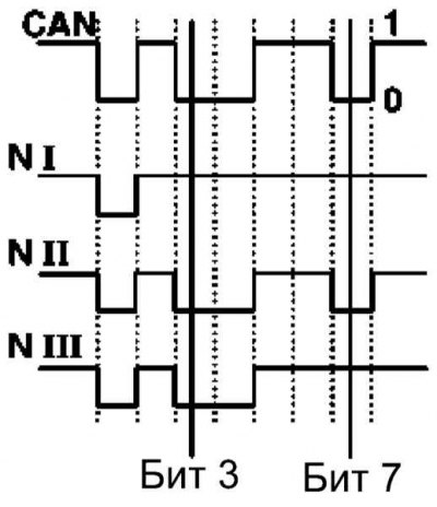
The first control block (NI) loses arbitration from bit 3.
The third control block (N III) loses arbitration from the 7th bit.
The second control unit (N II) retains access rights to the CAN data bus and can transmit its message.
Other control units will attempt to transmit their messages via the CAN data bus only after it is free again. In this case, the right to transmit will again be granted in accordance with the priority of the message via the CAN data bus.
Error recognition
Interference can cause errors in data transmission. Such errors that occur during transmission must be recognized and eliminated.
The CAN data bus protocol distinguishes between two levels of error recognition:
- data Frame level mechanisms (message frame);
- bit-level mechanisms.
Data Frame Level Mechanisms
Cyclic-Redundancy-Check
Based on the message transmitted via the CAN data bus, the transmitter unit calculates control bits, which are transmitted together with the data packet in the "CRC Field" field (checksums). The receiver unit recalculates these control bits based on the message received via the CAN data bus and compares them with the control bits received together with this message.
Frame Check
This mechanism checks the structure of the transmitted block (frame), that is, the bit fields with a given fixed format and the frame length are rechecked.
Errors detected by the Frame Check function are marked as format errors.
Bit-level mechanisms
Monitoring
Each module monitors the logic level of the CAN data bus when transmitting a message and determines the differences between the transmitted and received bits. This ensures reliable recognition of global and local bit errors occurring in the transmitter unit.
Bit Stuffing
In each data packet between the field "Start of Frame" and the end of the "CRC Field" field must be no more than 5 consecutive bits with the same polarity.
After each sequence of 5 identical bits, the block transmitter adds one bit with the opposite polarity to the bit stream.
Receiver units clear these bits after receiving a message on the CAN data bus.
Troubleshooting
If any CAN data bus module detects an error, it interrupts the current data transfer process by sending an error message. The error message consists of 6 dominant bits.
Thanks to the error message, all control units connected to the CAN data bus are notified of the local error that has occurred and accordingly ignore the previously transmitted message.
After a short pause, all control units will again be able to transmit messages via the CAN data bus, with the message with the highest priority once again being sent first.
The control unit whose CAN data bus message caused the error also begins retransmitting its message (automatic Repeat Request function).
CAN bus types
Different CAN buses are used for different control areas. They differ from each other in data transfer speed.
The transmission speed of the CAN data bus in the "engine and chassis" area (CAN-C) is 125 kbps, while the CAN data bus "Interior" (CAN-B) is designed for a data transmission speed of only 83 kbps due to the smaller number of particularly urgent messages. /With.
Data exchange between the two bus systems is carried out through so-called "gateways", i.e. control units connected to both data buses.
D2B fiber optic bus (Digital Daten-Bus) data is applied to the "Audio/communications/navigation" area. Fiber optic cable can transmit significantly more information than a copper cable bus.
CAN C - "Engine and chassis" bus
In the final control unit, a so-called data bus termination resistor with a resistance of 120 Ohm is installed on each side, connected between both data bus wires.
The engine compartment CAN data bus is only activated when the ignition is on.
7 control units are connected to the CAN-C bus.
CAN B - "Salon" bus
Some control units connected to the CAN data bus of the passenger compartment are activated regardless of whether the ignition is switched on (eg: single lock system).
Therefore, the CAN data bus of the passenger compartment must be in the functional readiness mode even when the ignition is off, which means that the ability to transmit data packets must be ensured even when the ignition is off.
In order to reduce the quiescent current consumption as much as possible, the CAN data bus, in the absence of data packets required for transmission, goes into passive standby mode and is activated again only the next time it is accessed.
If any control unit is in the passive standby mode of the passenger compartment CAN data bus (for example, a single lock control unit) transmits a message via the CAN data bus, then only the main system module receives it (electronic ignition switch, EZS). The EZS unit stores this message in memory and sends a wake-up signal to all control units connected to the CAN data bus of the passenger compartment.
When activated, EZS checks for the presence of all CAN data bus users and then transmits the previously stored message.
There are 20 control units connected to the CAN-B bus.
Elements of the Communication Area Network (CAN)
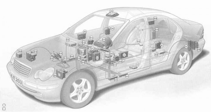
| CAN B (Salon) | |
| K1 | Front registration and control unit with fuse and relay box (SAM/SRB-V) |
| K2 | Rear Registration and Control Unit with Fuse and Relay Box (SAM/SRB-H) |
| K3 | Left Seat Control Module (SSG) |
| K4 | Right Seat Control Unit (SSG) |
| K5 | Front Left Door Control Unit (TSG) |
| K6 | Front Right Door Control Unit (TSG) |
| K7 | Rear Left Door Control Unit (TSG) |
| K8 | Rear Right Door Control Unit (TSG) |
| K9 | Roof Control Unit (DBE) |
| K10 | Upper control field (OBF) |
| K11 | Lower Control Field (UBF) |
| K12 | Electronic ignition start switch (EZS) |
| K13 | Instrument panel (KI) |
| K14 | COMMAND system/audio 10/audio 30/audio 30 APS |
| K15 | Parktronic system (PTS) |
| K16 | Trailer Hitch Device (AAG) |
| K17 | Multifunctional control unit for special models (MSS) |
| K18 | Parking heating |
| K19 | Heater (KKLA/BKLA – SA) |
| K20 | Distributor CAN-B RBA right |
| K21 | Distributor CAN-B RBA left |
| K22 | CAN-B Cockpit Distributor |
| K23 | Airbags with built-in ARMINCA call system |
| CAN C (Drive and chassis) | |
| K12 | Ignition Switch (EZS) |
| K13 | Instrument panel (KI) |
| K24 | Electronic gearbox control (EGS or KGS) |
| K25 | Engine Control Unit (MSG) |
| K26 | Electronic transmission unit (EMW) |
| K27 | Distributor CAN Class-C RBA left |
| K28 | Electronic skid control system (ESP) |
| Not included in the SG network | |
| K29 | Automatic Light Range Control (ALWR) |
| K30 | TV tuner |
Elements connected to the D2B fiber optic bus
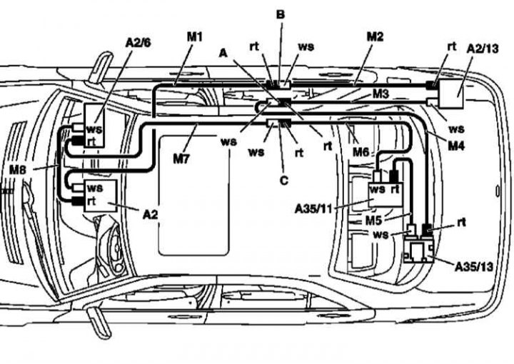
| D2B (Audio/Communication/Navigation) | |
| Fiber optic cable | |
| K14 | COMMAND/audio 10/audio 30/audio 30 APS |
| K31 | Telephone system (MINNA, emergency call) |
| K32 | Linguatronic Voice Control System (SBS) |
| K33 | Mobile Phone Controller (Interface) |
| K34 | Sound amplifier |
| K35 | CD changer |
| Not all are shown | |
| A2 | Radio or tape recorder |
| A2/6 | CD changer |
| A40/3 | Display and control unit for the operation of the COMAND system |
| A2/13 | Sound amplifier |
| A35/11 | Voice control system control unit |
| A59/1 | D2B interface for mobile/embedded phone |
| A35 | Cellular Telephone Transceiver (CTEL)/TELE AID Emergency Call System |
| A35/8 | TELE AID control unit |
| A, B, C | Connections |
| M1 | Fiber optic cable 1 |
| M2 | Fiber optic cable 2 |
| M3 | Fiber optic cable 3 |
| M4 | Fiber optic cable 4 |
| M5 | Fiber optic cable 5 |
| M6 | Fiber optic cable 6 |
| M7 | Fiber optic cable 7 |
| ws | White insert |
| rt | Red insert |