
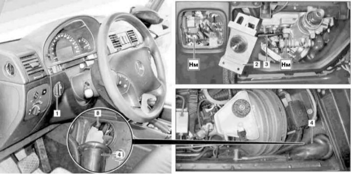
Details of installation of the handle of the drive for adjusting the tilt of the optical axes of the headlights
1 - switch handle; 2 - Mounting bracket; 3 - Remote sleeve; 4 - Bushing; 8 - Hole in bulkhead
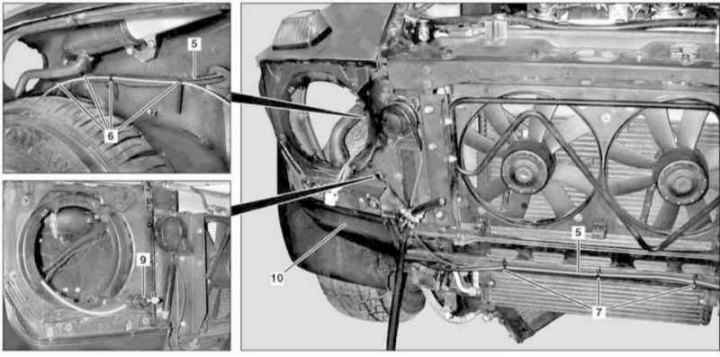
Details of installation of the executive device of the tilt of the optical axes of the headlights
5 - Control line; 6, 7 - Bandage clamps; 9 - Executive device; 10 - Lid
1. On models of the corresponding configuration (code ET2) activate the service mode of the TELE AID emergency call system (see Section Activation / deactivation of the service mode of the TELE AID emergency call system).
2. Turn on the auxiliary battery and connect it to the standard battery, then disconnect the negative cable from the latter.
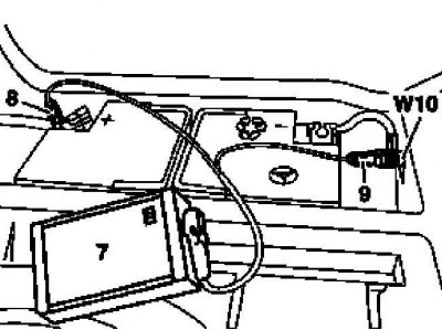
7 - Auxiliary battery
8 - Module positive wire terminal
9 - Terminal of the negative wire of the module
W10 - Battery Ground
3. Turn the handle (1) hydraulic corrector drive to position «0» and, without rotating, remove it from the instrument panel.
4. Remove the lower left section of the instrument panel trim (see chapter Body).
5. Remove the mounting bracket (2).
6. Remove the left group of switches of the panel of devices (see Section Group of switches on the left side of the instrument panel).
7. Remove the end cover of the steering column (see chapter Body).
8. Remove spacer (3).
9. Remove the front grille (see chapter Body).
10. Remove headlight (see Section Removal and installation of block headlights, replacement of lamps, adjustment of the direction of optical axes).
11. Remove the front bumper (see chapter Body).
12. Remove the wheel arch locker (see chapter Body).
13. Remove the front fixing screws and remove the cover (10) and a rubber seal installed under it.
14. Remove the brake booster assembly (see chapter Brake and auxiliary systems).
15. Open the grommet (4) and remove the foam rubber seal from it. Pulling forward, remove the bushing (4).
16. On models 463/323, remove the washer fluid reservoir (see chapter Body).
17. Release bandages (6 and 7) and separate the control line (5) from the wheel arch panel and the radiator transverse beam, - the bandages must be replaced without fail.
18. Push the governor actuator (9) through the window in the front panel and remove it from the vehicle by sliding it through the holes in the bulkhead (8) and wheel arch and releasing from the bushing (4), - try not to bend the hydraulic lines!
19. Installation is carried out in the reverse order - on models of the corresponding configuration (code ET2) deactivate the service mode of the TELE AID system (see Section Activation / deactivation of the service mode of the TELE AID emergency call system).
20. Finally, read the DTCs and clear the OBD memory using the STAR DIAGNOSIS scanner (6511 1801 00) (see chapter Engine Electrical Systems).
21. Check the correct adjustment of the tilt of the optical axes of the headlights, if necessary, make the appropriate adjustment (see Specifications).