
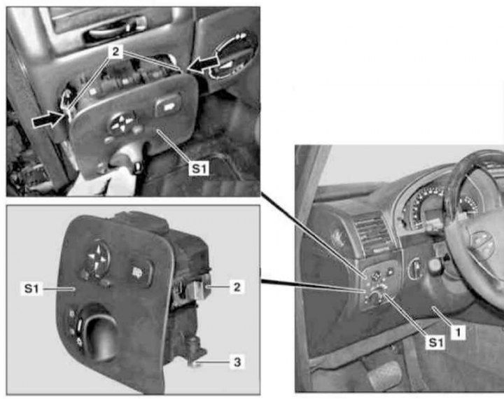
Installation details of the switch group on the left side of the instrument panel
1 - Left lower section of the instrument panel trim; 2 - Spring clips; 3 - Screw; S1 - Group of switches on the left of the instrument panel
1. On models of the corresponding configuration (code ET2) activate the service mode of the TELE AID emergency call system (see Section Activation / deactivation of the service mode of the TELE AID emergency call system).
2. Turn on the auxiliary battery and connect it to the standard battery, then disconnect the negative cable from the latter.
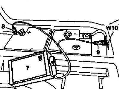
7 - Auxiliary battery
8 - Module positive wire terminal
9 - Terminal of the negative wire of the module
W10 - Battery Ground
3. Remove the left lower section (1) instrument panel trim (see chapter Body).
Note. The need to remove from the panel (1) electronic ignition switch control module (EIS/EZS) absent.
4. On models 463.246/249 of the corresponding configuration, remove the knee support (see chapter Body).
5. Turn out a fixing bolt (3), press the spring clips in the directions indicated by the arrows (2) and, prying with a suitable wedge, release the assembly of the switch group (S1) from the instrument panel.
6. Installation is carried out in the reverse order - on models of the corresponding configuration (code ET2) deactivate the service mode of the TELE AID system (see Section Activation / deactivation of the service mode of the TELE AID emergency call system).
7. Finally, read the DTCs and clear the OBD memory using the STAR DIAGNOSIS scanner (6511 1801 00) (see chapter Engine Electrical Systems) and enter the required basic settings for the on-board equipment.