
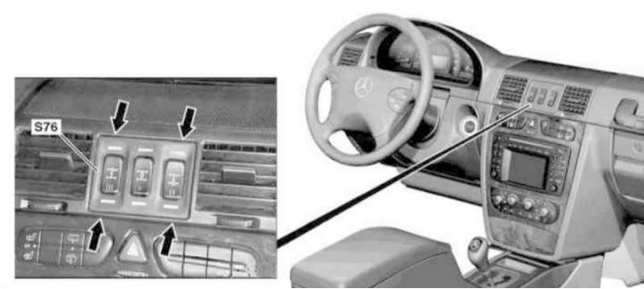
Installation details of the differential lock switch panel (S76)
1. Turn on the auxiliary battery and connect it to the standard battery, then disconnect the negative cable from the latter.
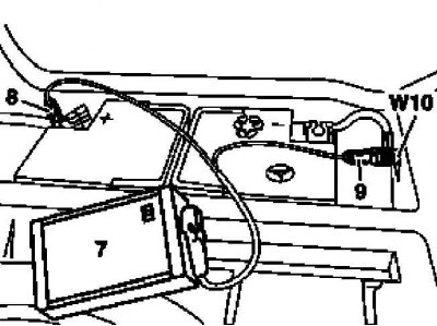
7 - Auxiliary battery
8 - Module positive wire terminal
9 - Terminal of the negative wire of the module
W10 - Battery Ground
2. Prying at four points (arrows) with a suitable long wedge, release the panel (S76) differential lock switches from the instrument panel.
3. Disconnect the electrical wiring from the back of the panel.
4. Installation is carried out in the reverse order.
5. Finally, read the DTCs and clear the OBD memory using the STAR DIAGNOSIS scanner (6511 1801 00) (see chapter Engine Electrical Systems).