
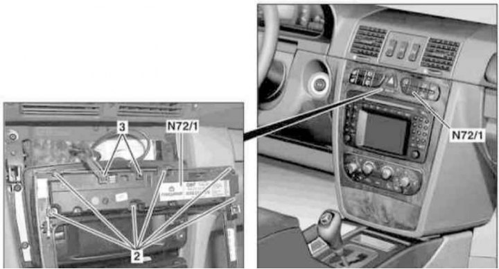
Installation details of the assembly of the upper groups of switches of the console part of the instrument panel
2 - Screws; 3 - Connectors; N72/1 - Assembly of switches
1. Turn on the auxiliary battery and connect it to the standard battery, then disconnect the negative cable from the latter.
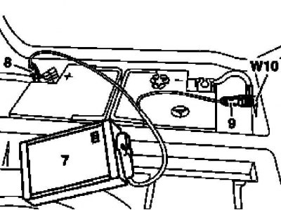
7 - Auxiliary battery
8 - Module positive wire terminal
9 - Terminal of the negative wire of the module
W10 - Battery Ground
2. Remove the facing panel of the console section of the instrument panel (see chapter Body).
3. Disconnect 2 (release models up to 09/30/01) /3 (release models from 09/30/01) connector (3) wiring.
4. Remove the fixing screws (2) and remove the assembly of the upper switch groups (N72/1).
5. Installation is carried out in the reverse order.
6. Finally, read the DTCs and clear the OBD memory using the STAR DIAGNOSIS scanner (6511 1801 00) (see chapter Engine Electrical Systems).