
Front bumper
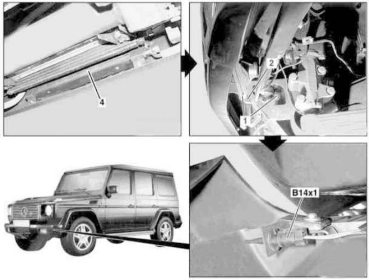
Front bumper installation details
1 - Bolts; 2 - Bumper; 4 - ATF cooler; B14x1 - Outside air temperature sensor connector
1. On models of the corresponding configuration (463.246) remove the lower engine compartment boot (see Section Removal and installation of an anther of an impellent compartment of a complete set AMG).
2. With the help of an assistant, remove the crankcase protection.
3. Remove the fog light (see chapter Onboard electrical equipment).
4. Remove from bumper (2) ATF cooler (4) (except AMG models).
5. On models 463.246 (AMG) remove from bumper (2) engine oil cooler and, without disconnecting the lines, move it to the side.
6. Turn out bolts (1).
7. Disconnect the connector (B14x1) outdoor temperature sensor wiring.
8. With the help of an assistant, remove the bumper (2).
9. Installation is carried out in the reverse order.
Rear bumper
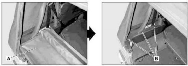
Preparing to remove the rear bumper (1 of 3) (except models 463.246)
A - Luggage compartment lid with wind deflector
B - Wind deflector mounting brackets
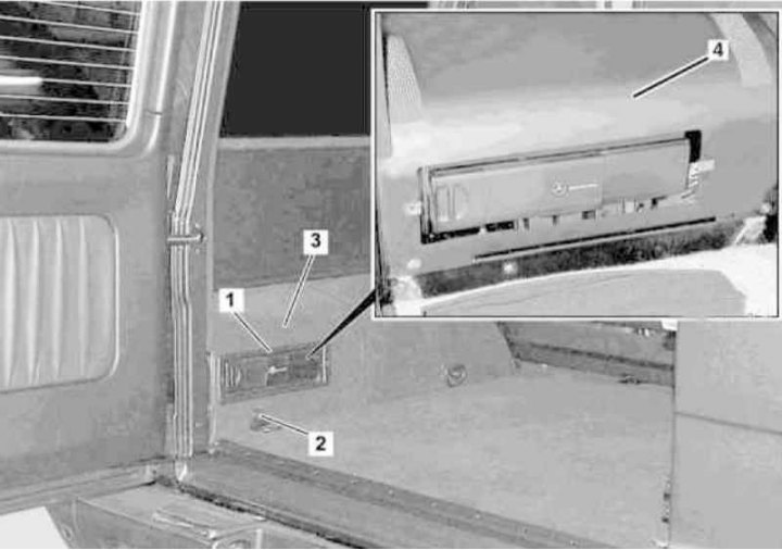
Preparing to remove the rear bumper (2 of 3)
1 - CD changer cover; 2 - Mounting eye; 3 - Floor covering; 4 - Lid
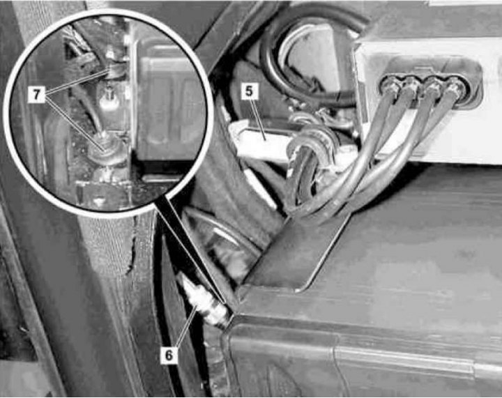
Preparing to remove the rear bumper (3 of 3)
5 - Wiring connector; 6 - Bolted connector; 7 - Rubber bushings
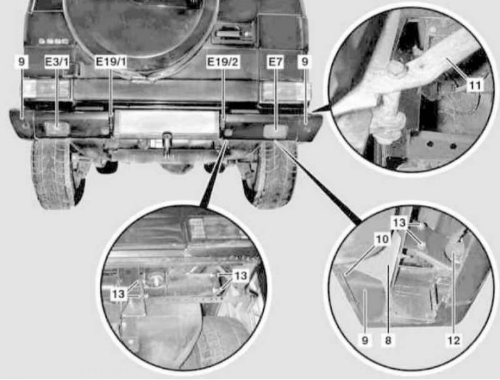
Rear bumper installation details
8 - splash guard; 9 - Corner pads; 10, 13 - Screws; 11 - Rack; 12 - connector; E7 - Reversing light; E3 / 1 - Rear; E19 / 1 - Left license plate light; E19 / 2 - Right license plate light
1. On models of the corresponding configuration (code ET2) activate the service mode of the TELE AID emergency call system (see Section Activation / deactivation of the service mode of the TELE AID emergency call system).
2. Remove 3 pushbuttons on each side and remove the cover (A) with wind deflector (except models 463.246).
3. On the left side, remove the mounting brackets (IN) wind deflector (except models 463.246).
4. Appropriate models (code V53) remove the storage compartment with a cover in the luggage compartment (see Section Removal, installation and adjustment of doors).
5. Appropriate models (code EP5) remove the cover (1) CD changer.
6. Unscrew the fixing eye (2).
7. Slightly lift the edge of the side trim panel and remove from the cover (4) carpet panel (3) floor coverings.
8. Remove the two fixing screws and remove the cover (4).
9. Appropriate models (code EP5) remove the CD changer.
10. Disconnect the connector (5) wiring harness going from the rear bumper to the passenger compartment of the car.
11. Appropriate models (code ET2) disconnect the threaded connector (6) replacement antenna of the TELE AID emergency call system.
12. Release the electrical wiring from the body panel by pulling it out through the grommet (7).
Note. Damaged bushings (7) must be replaced without fail.
13. Remove the splash guard (8).
14. Remove the screws (10), disconnect from the uprights (11) and remove the corner covers (9) bumper.
15. Disconnect the connector on the right (12) reversing light (E7).
16. On the left, disconnect the electrical wiring from the rear fog lamp (E3/1).
17. Remove the license plate lights (E19/1 and E19/2).
18. Remove the screws (13) (four on each side) and with the help of an assistant, remove the bumper.
19. Installation is carried out in the reverse order.
Note. Carpet flooring panel (3) attached to the lid (4) with glue.
20. Appropriate models (code ET2) deactivate the service mode of the TELE AID system (see Section Activation / deactivation of the service mode of the TELE AID emergency call system).
21. Finally, read the DTCs and clear the OBD memory using the STAR DIAGNOSIS scanner (6511 1801 00) (see chapter Engine Electrical Systems).