
Attention! All self-locking fasteners must be replaced without fail!
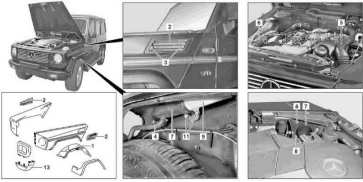
Front fender installation details (1 of 3)
1 - Locker; 2 - Air intake grille; 3, 8, 11 - Bolts; 4 - Drainage hose; 5, 6, 7, 9 - Air intakes; 13 - Lid
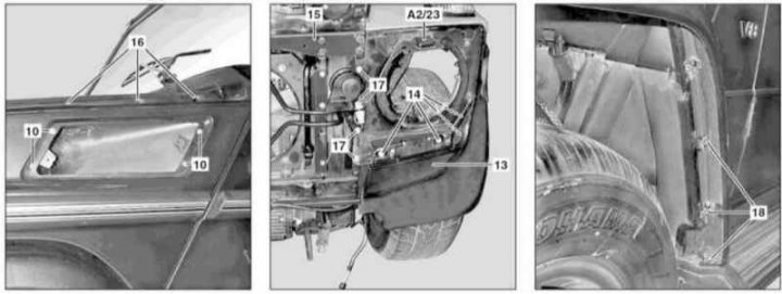
Front fender installation details (2 of 3)
10 - Screws; 13 - Cover; 14, 16, 17, 18 - Bolts; 15 - Upper transverse bulkhead; A2/23 - GPS Antenna
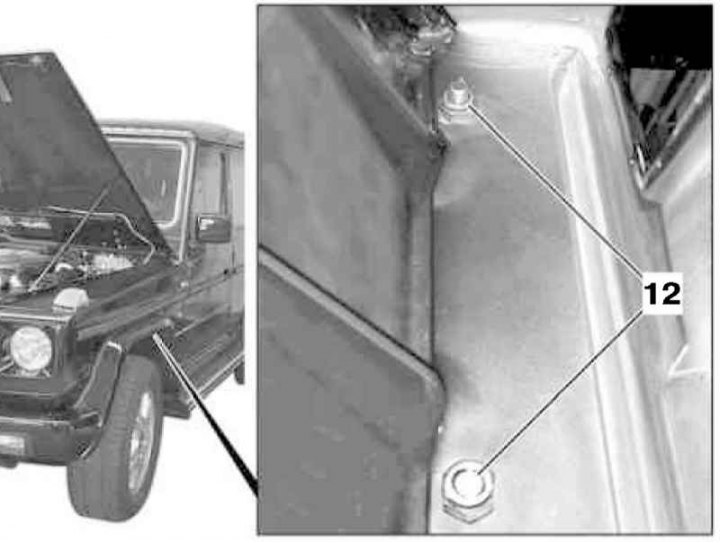
Front fender installation details (3 of 3)
12 - Nuts
1. Open the hood and move it to a vertical position (see Section Removal and installation of a cowl).
2. Remove the front grill (see Section Removal and installation of a forward lattice).
3. Remove the headlight assembly (see chapter Onboard electrical equipment).
4. Remove the wheel arch locker (1).
5. Remove the differential lock drive vacuum reservoir (left wing).
6. On models 463.323, remove the washer fluid reservoir (left wing).
7. Turn out bolts (3) and remove the air intake grille (2) (on models 463.323 only on the right fender).
8. Remove the drain hose (4).
9. Turn out bolts (8) and remove the air intakes (5 and 6) (on models 463.3223 only on the right fender).
10. Remove the screws (10) and remove the air intake from the wing (9) (on models 463.3223 only on the right fender).
11. Loosen the bolt (11) fixing the air duct to the wheel arch (on models 463.3223 only on the right fender).
12. Remove the turn signal (see chapter Onboard electrical equipment), - on models 463.246 (AMG) additionally disconnect the wiring connector (E6/3 or E6/4) corresponding position light.
13. Appropriate models (codes EF4 and ET4) remove the GPS navigation system antenna (A2/23), - only on the left wing.
14. Remove the crankcase protection.
15. If equipped, remove the boot of the engine compartment (see Section Removal and installation of an anther of an impellent compartment of a complete set AMG).
16. Turn out bolts (14) and remove the cover (13).
17. Remove the upper transverse bulkhead (15).
18. Remove the expansion tank of the cooling system (see chapter Refrigeration, heating, ventilation and air conditioning systems), - right wing only.
19. Remove the resonator chamber with water collector (see chapter Power supply and exhaust systems), - right wing only.
20. On models 463.250, remove the antenna splitter (right wing only) and, without disconnecting the antenna cable, take it aside.
21. Remove the washer fluid reservoir (except models 463.323), - right wing only.
22. On models 463.246 (AMG) release, but do not disconnect, the headlight hydrocorrector line.
23. Release the top eight (16) and four front (17) wing bolts.
24. Remove the bolts (18) fastening the lining of the arch.
25. Give nuts (12) attaching the wing to the bulkhead of the engine compartment.
26. Filing forward, remove the wing - use the help of an assistant.
27. Installation is carried out in the reverse order.