
Removal and installation
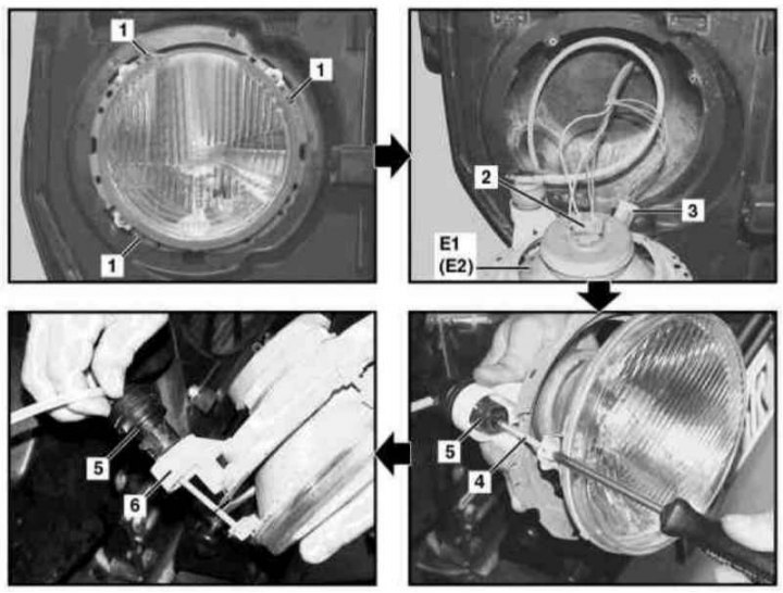
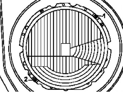
Headlight installation details
1 - Bolt; 2, 3 - Wiring connectors; 3 - Nuts; 4 - Adjusting screw; 5 - Regulator; 6 - Support bracket; E1 - Left block headlight; E2 - Right block headlight
1. Remove headlamp cover (see chapter Body).
2. Remove the bolt (2) and remove headlights (E1/E2).
3. Disconnect the connector (2) high/low beam wiring.
4. Disconnect the connector (3) electrical wiring for marker/parking lights.
5. Completely turn out the adjusting screw (4) regulator (5) position of the headlight, turn the regulator to the left and remove from the support bracket (6), - try not to kink the hydraulic line.
6. Installation is carried out in the reverse order.
7. In conclusion, check the correct installation of the optical axes of the headlights, if necessary, make the appropriate adjustment (see below).
Replacing headlight bulbs
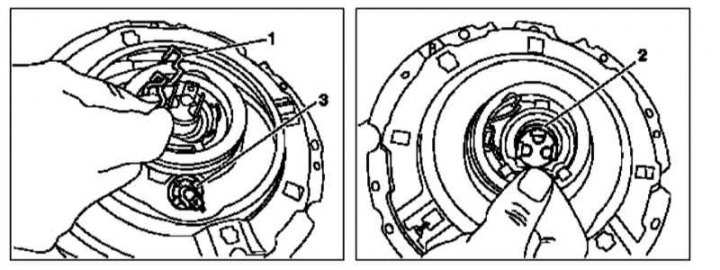
1 - Spring retainer; 2 - Low / high beam lamp; 3 - Lamp marker / parking light
1. Remove headlight (see above).
2. Remove the rubber back cover.
3. Release the spring clip and remove the dipped / main beam lamp from the guides (2), - try not to touch the lamp bulb with bare hands.
4. Pull out the position/parking light bulb from the reflector (3), - also try not to touch the flask with bare hands.
5. Installation is carried out in the reverse order.
Adjusting the inclination of the optical axes of the headlights
Note. Adjustment is made on an unloaded car with an occupied driver's seat (load weighing 75 kg).
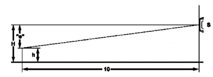
Adjustment of the inclination of the optical axes of the headlights is carried out using a test board
10 - Distance in meters; e - Adjustment range (see Specifications); H - The height of the position of the center of the headlight; h - Height of the position of the cut line of the working area of the shield; S - block headlight
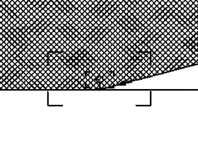
An example of the illumination of the working area of the test board
Location of adjusting screws
1 - Adjustment in the vertical plane
2 - Adjustment in the horizontal plane
1. Check for correct tire inflation (the required values are indicated on the inside of the fuel filler cap).
2. Remove outer covers (facing frames) block headlights (see Section Removal and installation of covers of block headlights).
3. Set the handle of the headlight hydrocorrector switch on the left on the instrument panel to the position «0».
4. The check must be carried out in a car service workshop using a special test board installed at a distance of 10 meters in front of the headlight being checked, strictly in accordance with the manufacturers' instructions.
5. The adjustment is considered correct if the cutoff line of the light spot generated by the headlight switched on in the dipped beam mode is aligned with the horizontal markings (cutting line) working area of the shield to the left of its center. If necessary, make appropriate adjustments using the vertical (1) and horizontal (2) regulators.