
- a clutch control unit, consisting of a control mechanism, an actuating motor and a clutch actuating cylinder;
- steering angle sensors to determine the direction of rotation and a gear change mechanism;
- central hydraulic clutch with hydraulic cylinder;
- clutch disc;
- self-adjusting pressure plate (see illustration 4.0).
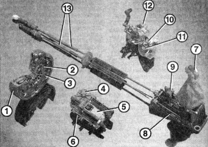
4.0 Automatic transmission control mechanism
1 - flywheel
2 - clutch disc
3 - self-adjusting pressure plate
4 - clutch drive
5 - executive electric motor
6 - control unit
7 - gear lever
8 - gear shift mechanism
9 - angle sensor on the gear shift mechanism
10 - angle sensor on gear shift rods
11 - angle sensor on gear selection rods
12 - enable module
13 - cable traction
Instead of conventional clutch rods, there is a hydraulic element under the shift lever (drive unit), consisting of an executive electric motor with a cylinder, which is controlled by an electronic unit.
The hydraulic block performs the function of an ordinary clutch.
Gear shifting and clutch mechanics are largely similar to manual transmission models. The self-adjusting pressure plate compensates for wear on the clutch disc and keeps the kinematic relationship at a constant level.
After switching the lever by the driver, this action is transmitted to the control unit by means of various sensors. Taking into account other information received from the engine control unit, the clutch control system regulates the clutch process. To this end, it sends impulses to the actuator motor, which ensures the clutch process via the central hydraulic clutch.
The hydraulic clutch system is provided with brake fluid from the expansion tank of the brake system.
The automatic clutch control unit has a self-diagnostic function, which makes it possible to read the fault codes registered by the unit.
Codes can be read and printed using a special diagnostic tester. Diagnosis and repair of the clutch should be entrusted to the specialists of the appropriate workshop.