
Release models up to 08/31/99
Release models from 09/01/99
Lubrication scheme (release models up to 08/31/99) |  |
Lubrication scheme (release models from 09/01/99) | 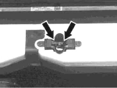 |
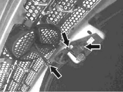
1. Details of the installation of the lock components are shown in the illustration, to which all references in the text refer.
2. Open the hood and lock it in an upright position.
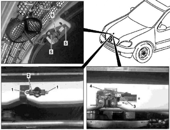
3. Remove the screws (1) and, pulling up, remove the lower section (2) castle assembly.
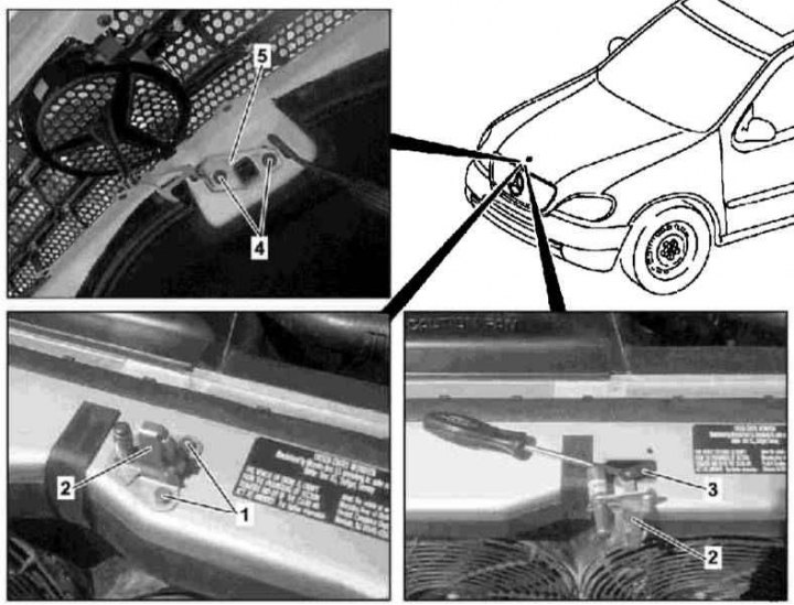
4. Remove the latch release lever on the left under the instrument panel in the passenger compartment and disconnect the drive cable from it (models up to 31.08.99) /disconnect the electrical wiring connector (4) (models from 01.09.99).
5. Disconnect the latch release cable (3) from bottom section (2) lock assembly and remove the latter from the cross beam.
6. Remove the screws (4 and 5) and remove the top section (6) lock, on models up to 08/31/99 equipped with a safety lock.
7. Installation is carried out in the reverse order.
8. Finally, adjust the position of the hood (see Section Removal, installation and adjustment of a cowl), make sure that it is securely fixed in the closed position and lubricate the exposed elements of the lock assembly with grease (including safety hook) and loops. Check the freedom and smoothness of the safety hook.
Latch release cable
Details of installation of a drive cable of release of a latch of the lock of a cowl
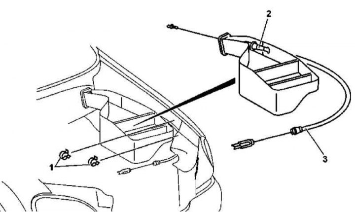
1. Details of the installation of the drive cable for releasing the latch of the hood lock are shown in the illustration, which includes all references in the text.
2. Open the hood and lock it in an upright position.
3. Remove the upper frame cross member (see Section Removal and installation of the upper front transverse beam of the frame).
4. Remove the hood latch (see above).
5. Release the drive cable from the intermediate clips under the top cross member of the frame.
6. Remove the fixing screws/release the clips and remove the cover of the fuse/relay mounting block (see chapter Onboard electrical equipment).
7. If necessary, remove intermediate fasteners (1) drive cable laying.
8. Remove the cover on the left under the instrument panel (see Section Removal and installation of the lower covers of the panel of devices).
9. Remove left footwell trim panels (see Section Removing and installing front footwell trim panels).
10. Release the drive cable from the retainer on the well wall.
11. Remove bushing (2) cable from the fuse/relay mounting block.
12. Retract drive cable (3) through the bulkhead into the engine compartment.
13. Installation is carried out in the reverse order - follow the correct laying of the cable.