
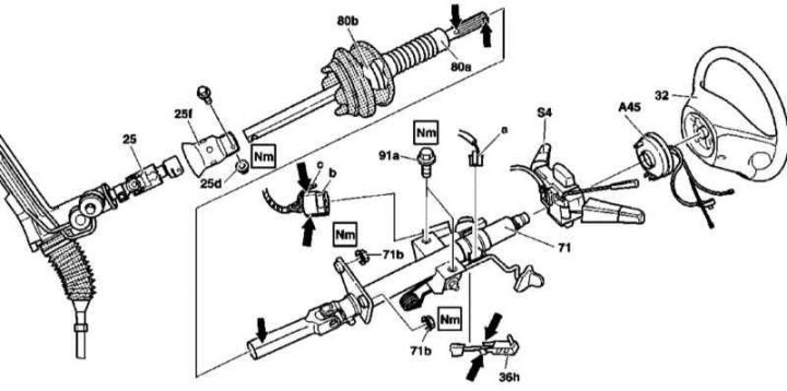
Steering column design
25 - Input node of the steering mechanism; 25d - Self-locking nut; 25f - Casing; 32 - Steering wheel; 36h - Shift lock (AT); 71 - Shirt; 71b - Bottom nuts; 80 - Lower shaft; 80a - Anther; 91a - Top bolts; A45 - Spiral contact drum; S4 - Combined steering column switch; a - Electrical wiring connector of the switch; b - Contact connector; c - Transponder
Note. All self-locking bolts and nuts must be replaced without fail!
1. The design of the steering column is shown in the illustration, to which all references in the text refer.
2. Disconnect the negative cable from the battery.
3. Remove the steering wheel (32) and spiral contact drum (A45) (see Section Removal and installation of a steering wheel and a spiral contact drum of a steering column).
4. Remove the combination switch (S4) (see chapter Onboard electrical equipment).
5. Remove the instrument cluster (see chapter Onboard electrical equipment).
6. Disconnect the connector (A) adjustment lever.
7. On models with AT, remove the switch lock from the steering column lock (36h), - squeeze the latches and pull the blocker back, removing it from the fixing clips.
8. Disconnect the connector (With) and remove the transponder.
9. Release the lock and disconnect the connector (b).
10. Release the latches securing the combination steering column assembly (S4) and remove the latter from the steering column jacket (71).
11. Remove the cover on the left under the instrument panel.
12. Give the lower nuts (71b) and remove the top bolts (91a) shirt fasteners (71).
13. Squeeze up, take off your shirt (71).
14. Give the self-locking nut (25d) fixing bolt and separate the lower shaft of the steering column (80a) from the input node (25) rack and pinion - do not resort to force, if necessary, slightly open the lock with a screwdriver!
15. Filing up, remove the steering shaft (80a).
16. Check the condition of the shaft (80a), replace if necessary.
17. Replace damaged boot (80b), - check the correct fit of the anther.
18. If the shirt needs to be replaced, remove the ignition lock cylinder (see Section Removal and installation of the cylinder of the lock of ignition).
19. Installation is carried out in the reverse order - follow the correct fit of all components. First, tighten all fasteners so that the position of the jacket can be corrected, then, having achieved the desired result, tighten the upper bolts with the required force first, then the lower nuts. Track reliability of fixing of contact sockets.