Removal
1. Disconnect the corrugated cover of the wiring harness from the front pillar 2 (see illustration).
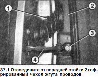
2. Disconnect the multi-pin plug located under the cover by turning it to the right.
3. Unscrew bolt 3 and disconnect door travel limiter 4 from the front pillar (see illustration 37.1).
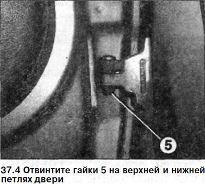
4. Unscrew nuts 5 on the upper and lower door hinges (see illustration).
5. Remove the front door from its hinges, working with an assistant.
Installation
The door is installed in the reverse order of removal.
Tightening torques for threaded connections:
- door opening limiter to the front pillar - 30 Nm
- door to door limiter - 10 Nm
- door hinge fastening nut - 8 Nm
6. Fit the installed door.
Fitting the front door
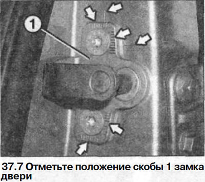
7. Mark the position of bracket 1 of the door lock (see illustration)For this purpose, marks are applied to the bracket and the central pillar (see arrows in illustration 37.7). If the lower marks on the central pillar are not visible, apply new marks with a felt-tip pen.
8. Unscrew the bracket mounting bolts and remove the bracket.
9. Check the width of the gaps between the front door and adjacent body parts.
Nominal clearance dimensions:
- The gap between the door and the roof is 5.0±0.5 mm
- The gap between the door and the front pillar is 6.5±0.5 mm
- The gap between the front and rear doors is 5.0±0.5 mm
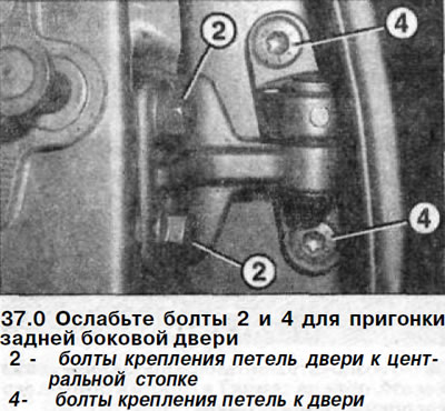
10. Loosen bolts 2 securing the door hinges to the front pillar 3 so that the door can be moved (see illustration).
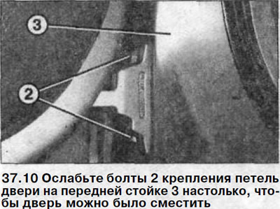
11. Move the front door so that the gap width corresponds to the nominal one and tighten the bolts with a force of 32 Nm.
12. Loosen the bolts 4 that secure the hinges to the door 5, so that the door can be moved (see illustration).
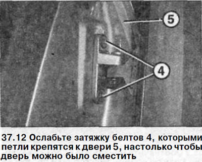
13. Move the door so that its outline coincides with the outline of the wing or is no more than 1 mm lower than it and tighten the bolts with a force of 32 Nm.
14. Install the lock bracket as it was before removal, using the marks as a guide. Do not tighten the bracket bolts so that the bracket can be moved by applying a certain amount of force.
15. Close the door and, by moving the lock bracket, adjust it so that its outline matches the outline of the rear door or is no more than 1 mm lower.
16. Carefully open the door and tighten the lock bracket mounting bolts to 28 Nm.
17. Check the fit and adhesion of the door near the window opening relative to the roof and the front pillar. If necessary, repeat the door adjustment.
18. Open and close the door several times, checking for ease of movement.
If necessary, repeat the door adjustment. The rear side door is adjusted in an identical manner. To adjust the door, loosen bolts 2 and 4, respectively (see illustration 37.0).