
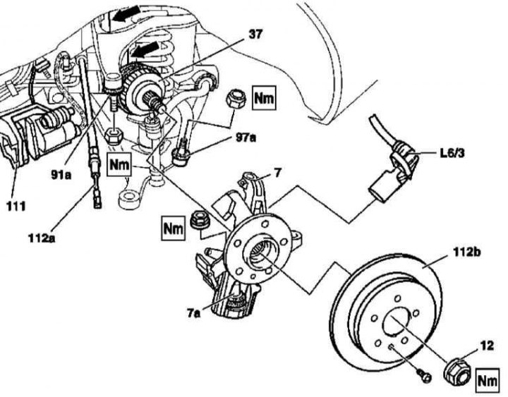
Installation details of the rear hub assembly
7 - Hub assembly; 7a - Lower ball joint; 12 - Hub nut; 37 - Drive shaft; 91a - Upper ball joint; 97a - Stretching hinge; 111 - Brake caliper; 112a - Parking brake cable; 112b - Brake disc; L6 / 3 - Left rear wheel sensor
1. The installation details of the rear hub assembly are shown in the illustration, to which all references in the text refer.
2. Apply the parking brake and remove the hub nut (12).
3. Remove the appropriate rear wheel.
4. Remove wheel sensor (L6/3 in case of left wheel).
5. Remove the brake caliper (111) (see chapter Brake and auxiliary systems).
6. Remove heat disc (112b) (see chapter Brake and auxiliary systems).
7. Remove parking brake shoes (see chapter Brake and auxiliary systems).
8. Release the parking brake cable from the support bracket on the hub assembly (112a).
9. Using a puller, release the brace joint from the hub assembly (97a).
10. Press the ball joint out of the hub assembly (91a) upper suspension arm.
11. Using an extractor, press the rear drive shaft out of your flange - try not to damage the CV joint boot and the wheel sensor rotor. Tie up the released shaft to the suspension/frame members.
12. Having fixed the hub assembly, release the shank of the lower ball joint (7a) from the control arm.
13. Remove the hub assembly.
14. Installation is carried out in the reverse order, in conclusion, make the necessary adjustments to the angles of the wheels.
Ball joint replacement
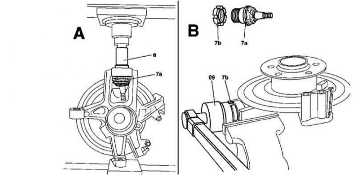
Installation details of the lower ball joint in the steering knuckle
1. The installation details of the lower ball joint are shown in the illustration, to which all references in the text refer.
2. Remove hub assembly (see above) and press out the lower ball joint (7a) with a suitable mandrel (A).
3. Using a special key (9) give the lock nut (7b).
4. Using a castle nut and a special wrench, press in a new ball joint until it stops in the hub assembly, - replace the nut.
5. Install the hub assembly in its original place.