



Contents: Front drive shafts ↡ Rear drive shafts ↡
Attention! All self-locking bolts/nuts must be replaced without fail!
Front drive shafts
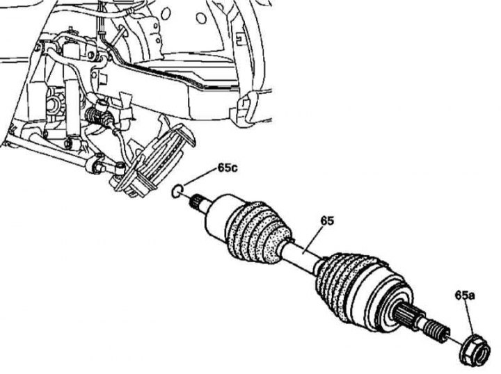
Front Drive Shaft Installation Details
1. Front drive shaft installation details are shown in the illustration to which all references in the text refer.
2. Remove the appropriate wheel.
3. Loosen the hub nut (65a) - the nut must be replaced without fail.
4. Without disconnecting the flexible hose, remove the brake caliper (see Chapter Brake and auxiliary systems).
5. Disconnect the steering rod from the steering knuckle.
6. Using a puller, release the ball joint from the upper wishbone. Check the condition of the boot, assess the degree of wear of the joint, and replace the ball joint if necessary.
7. Using an extractor, press the drive shaft (65) out of the hub flange, - tie the steering knuckle to the suspension or frame elements.
Article was obtained from the portal www.MercedesMan.ru
8. Using a lever, release the drive shaft (65) from the front axle differential and remove it from under the vehicle. Check the condition of the hinge assembly boots, assess the degree of wear of the latter, and replace the shaft assembly if necessary.
9. Installation is carried out in the reverse order - make sure that the retaining ring (65c) is turned with the lock facing down when installing the shaft.
Rear drive shafts
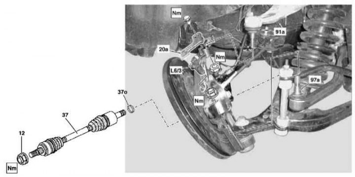
Rear Drive Shaft Installation Details
12 - Hub nut; 20a - Wheel sensor support bracket; 37 - Drive shaft; 37o - Retaining ring; 91a - Upper ball joint; 97a - Stretch joint; L6/3 - Left wheel sensor
1. Front drive shaft installation details are shown in the illustration to which all references in the text refer.
2. Remove the appropriate wheel.
3. Apply the parking brake and loosen the hub nut (12) - the nut must be replaced without fail.
4. Separate the wheel sensor support bracket (20a) from the hub assembly and remove the sensor (L6/3, - in case of left wheel).
5. Using a puller, release the ball joint (91a) of the upper wishbone from the hub assembly. Check the condition of the boot, assess the degree of wear of the joint, and replace the ball joint if necessary.
6. Press the tensioner joint (97a) out of the hub assembly.
7. Release the drive shaft (37) from the hub flange - use a puller if necessary, try not to damage the wheel sensor rotor boot.
8. Release the drive shaft (37) from the front axle differential and remove it from under the vehicle. Check the condition of the hinge assembly boots, assess the degree of wear on the latter, and replace the shaft assembly if necessary.
9. Installation is carried out in the reverse order - make sure that the retaining ring (65c) is turned with the lock facing down when installing the shaft.