



Open a larger image in a new tab »
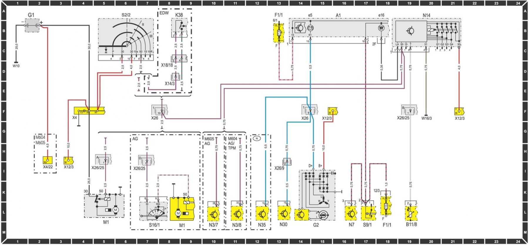
Key to the electrical circuit diagram
| Index | Schematic element | Coordinates |
| A1 | Combination device | 16A |
| A1e5 | Charge Control/Generator Warning Light | 14A |
| A1e16 | Preheating control emitter | 18A |
| B11/8 | Coolant temperature sensor, electric torch device | 19M |
| C2 | Interference-proof wiring generator-battery | 4F |
| F1/1 | 12-pin fuse socket in relay and fuse box | F1 |
| F1/1-6 | Fuse 6, terminal 15 | 13B |
| F1/1-12 | Fuse 12, terminal 15 | 18L |
| G1 | Battery | 2A |
| G2 | Generator | 15M |
| K38 | Starter Disable Relay (EDW) | 8A |
| M1 | Starter | 5M 9M |
| N3/7 | ERE device | 10M |
| N3/8 | EVE device | 11M |
| N7 | Lamp control device | 16M |
| N14 | Preheating relay | 20A |
| N30 | ABS device | 13M |
| N35 | Daytime running light device | 12M |
| S2/2 | Heating start switch | 6A |
| S9/1 | Brake light switch, 4-pole | 17M |
| S16/1 | Start inhibit switch and reverse light switch | 7M |
| W10 | Battery ground terminal | |
| W16/3 | Engine compartment ground terminal on the left, ground bus ground terminal without marking, directly on the engine, respectively, body | |
| X4 | Terminal block 30, 3-pole, near the feet on the left | 4F |
| X4/22 | 1-pole terminal plug 30Z | 2I |
| X12/3 | Open 3-pole terminal block 30/15 | 3I 15F 21F |
| X14/3 | 1-pole terminal plug 50/EDW | 8E |
| X18/18 | 4-pole plug connection for warning buzzer (cabin/ infrared) | 8D |
| X26 | Plug connection passenger compartment/engine, | 7F 14F |
| X26/9 | 8-pin plug connection interior/units | 13I |
| X26/25 | 24-pin plug connection engine/body | 5I 7I |
| Wire diameters may differ from those shown. | ||
[Original published on the website MERCEDESMAN.ru]