



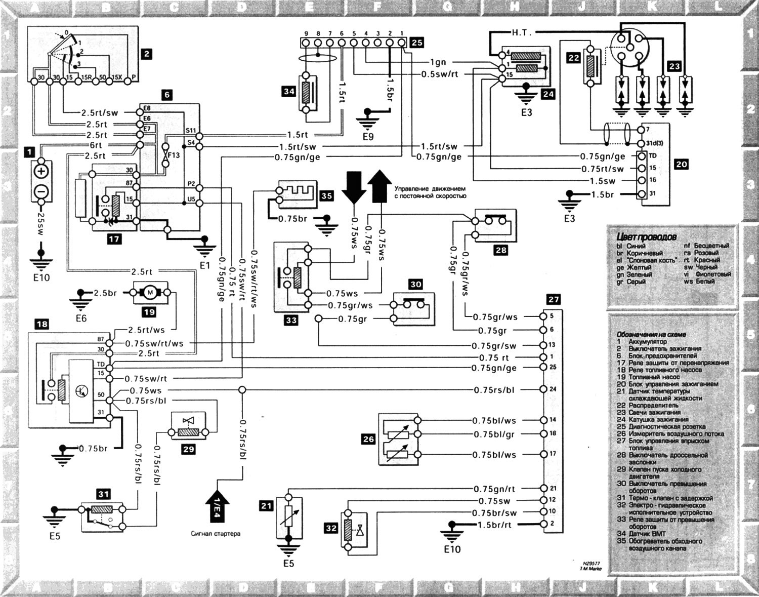
Typical engine management system
Open a larger image in a new tab »
Designations on the diagram: 1. Battery; 2. Ignition switch; 6. Fuse box; 17. Overvoltage protection relay; 18. Fuel pump relay; 19. Fuel pump; 20. Ignition control unit; 21. Coolant temperature sensor; 22. Distributor; 23. Spark plugs; 24. Ignition coil; 25. Diagnostic socket; 26. Air flow meter; 27. Fuel injection control unit; 28. Throttle switch; 29. Cold engine start valve; 30. Overspeed switch; 31. Thermovalve with delay; 32. Electrohydraulic actuator; 33. Overspeed protection relay; 34. TDC sensor; 35. Bypass air duct heater
Symbol designations on diagrams, grounding points and fuses are located here →
(Original source of information: www.MercedesMan.ru)