



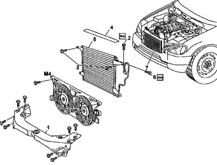
Installation details of the K/V capacitor
1 - Upper front cross member of the frame; 2 - Bolt; 3 - Bolts; 4 - Rubber seal; 5 - Capacitor; 6 - Bolt; 7 - Radiator; M4 - Auxiliary Fan Assembly (with appropriate equipment)
Attention! All sealing elements must be replaced.
1. The details of the installation of the K/V capacitor are shown in the illustration, to which all references in the text refer.
2. On models 163.136/154/157/172, remove the auxiliary fan assembly (M4) (see Section Removal and installation of auxiliary fan assembly, - models 163.136/154/157/172 of the corresponding configuration).
3. On models 163.112/128, remove the charge air cooler (see Section Removal and installation the cooling system radiator).
4. In a car service workshop, discharge the cooling system.
5. Loosen the screw (2) and disconnect the refrigeration line from the receiver-dryer.
6. Remove screw (6) and disconnect the refrigeration line from the condenser (5).
7. Remove the rubber seal (4) from the cooling system radiator (7).
8. Unscrew the mounting bolts (3) and, pulling upwards, remove the K/V capacitor (5).
9. Installation is carried out in the reverse order - the air conditioning system must be filled in a car service workshop.