



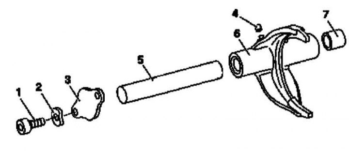
Design of the transfer case mode switching drive
1 - Bolt; 2 - Washer; 3 - End cap; 4 - Insert; 5 - Shift rod; 6 - Shift fork; 7 - Bearing
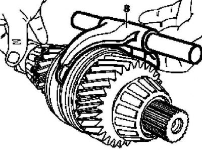
Shift fork mounting diagram
8 - Assembling the rod with the shift fork
1. Remove the transfer case (see Section Removal and installation the transfer case).
2. Remove the transfer case servomotor (see Section Removal and installation the transfer case servomotor).
Material based on data from the portal: MercedesMAN.ru
3. Remove the shift fork assembly with the rod (8).
4. Installation is carried out in the reverse order - do not forget to thoroughly wipe all components beforehand.