
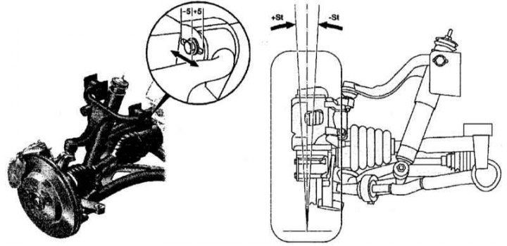
Checking and adjusting the camber of the front wheels
ST + - Positive camber
ST - - Negative camber
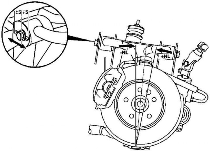
Checking and adjusting the run-out of the front wheels
NL - Coast down
Examination
1. Make the necessary preliminary checks (see Section Vehicle wheel alignment - general information).
2. Check that the axle clearances are correct (see Section Checking and adjusting ride height), make appropriate adjustments if necessary.
3. Measure the camber and runout angles.
Note. The runout is measured with the wheels turned out at an angle of 20°. Compare measurement results with requirements Specifications, make appropriate adjustments if necessary.
Adjustment
1. Adjustment of the camber of the front wheels is made using bolted connections for fastening the rear corners of the upper transverse levers to the side beams of the frame.
2. Bolted connection of the front corners of the upper arms to the frame allows for run-out adjustment.
3. In conclusion, also adjust the toe-in (see Section Checking and adjusting convergence).
Rear wheels
The corresponding illustrative material is presented in Ref. illustrations, which include all references in the text.
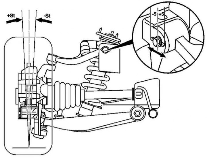
Checking and adjusting the camber of the rear wheels
+ ST - Positive camber
-ST - Negative camber
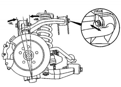
Checking and adjusting the runout of the rear wheels
NL - Coast down
Checking and adjusting the runout of the rear wheels
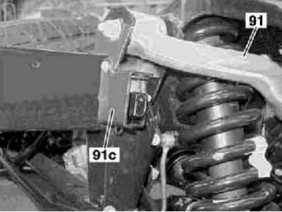
91 - Upper longitudinal extension
91c - Mounting plate
Examination
1. Make the necessary preliminary checks (see Section Vehicle wheel alignment - general information).
2. Check that the axle clearances are correct (see Section Checking and adjusting ride height), make appropriate adjustments if necessary.
3. Measure the camber and runout angles.
Note. The overrun is measured using an electronic inclinometer. Compare measurement results with requirements Specifications, make appropriate adjustments if necessary (see below).
Adjustment
1. Adjustment of the camber of the front wheels is carried out using bolted connections for fastening the front corners of the upper transverse levers to the side beams of the frame.
Note. On models equipped with xenon headlights, remove the retaining plate (91s) away from the frame and set aside along with the landing level sensor.
2. Bolted connections of fastening of back corners of the top levers to a frame allow to carry out adjustment of run-out of wheels.
3. Finally, also adjust the convergence (see Section Checking and adjusting convergence).