



Contents: Rear doors ↡ Tailgate ↡
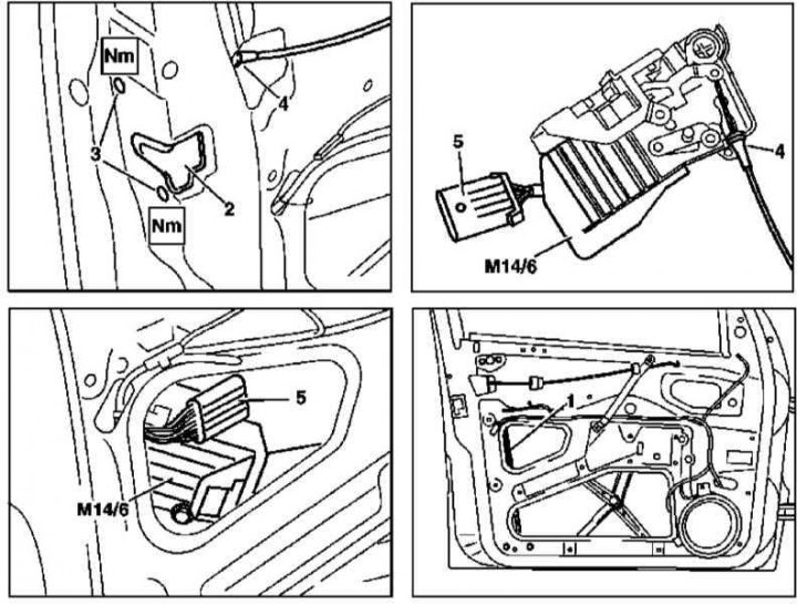
Front door lock assembly installation details
1. The installation details of the front door lock assembly elements are shown in the illustration, to which all references in the text refer.
2. Remove the inner door trim and sealing film (see Section Removal and installation interior trim panels of door assemblies).
3. Remove the outer door handle and its supporting bracket (see Section Removal and installation exterior door handles).
4. Remove the window regulator guide channel (1).
5. Remove the mounting screws (3).
6. Disconnect the contact connector (5) of the door actuator drive electric motor wiring (M14/5 or M14/6).
7. Lower the lock assembly (2) down and remove it from the door frame through the service window.
8. Disconnect the drive cable (4).
9. Installation is carried out in the reverse order - the damaged sealing film should be replaced.
Rear doors
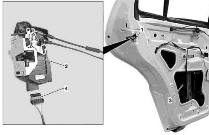
Rear door lock assembly installation details
1. The installation details of the rear door lock assembly components are shown in the illustration, to which all references in the text refer.
2. Remove the inner door trim and sealing film (see Section Removal and installation interior trim panels of door assemblies).
3. Remove the outer door handle and its supporting bracket (see Section Removal and installation interior trim panels of door assemblies).
4. Close the door glass completely.
5. Disconnect the electrical wiring connector (4).
6. Remove the mounting screws (1) and carefully remove the lock assembly (2) through the service window (3) in the door frame - the window lifter guide channel should be slightly moved forward to allow the lock to pass underneath it.
7. Installation is carried out in the reverse order - make sure that the window lifter guide channel is seated correctly. A damaged sealing film should be replaced.
Tailgate
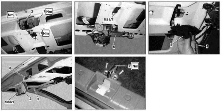
Details of installation of elements of the lock assembly of the tailgate
4 - Bolt; 5 - Door interior trim; M14/7 - Drive motor for tailgate lock actuator
1. The installation details of the rear door lock assembly elements are shown in the illustration, to which all references in the text refer.
2. Remove the inner door trim (see Section Removal and installation interior trim panels of door assemblies).
3. Disconnect the rod (3) from the door handle (6).
4. On models produced up to 31.08.99, disconnect the electrical wiring connector (8) of the toggle microswitch (S88/1).
5. Remove the door lock (2) and striker (7), having first marked the position of the latter.
6. Installation is carried out in the reverse order - make sure that the lock striker (7) is seated correctly. If necessary, adjust the door seat in the body opening (see Specifications).