



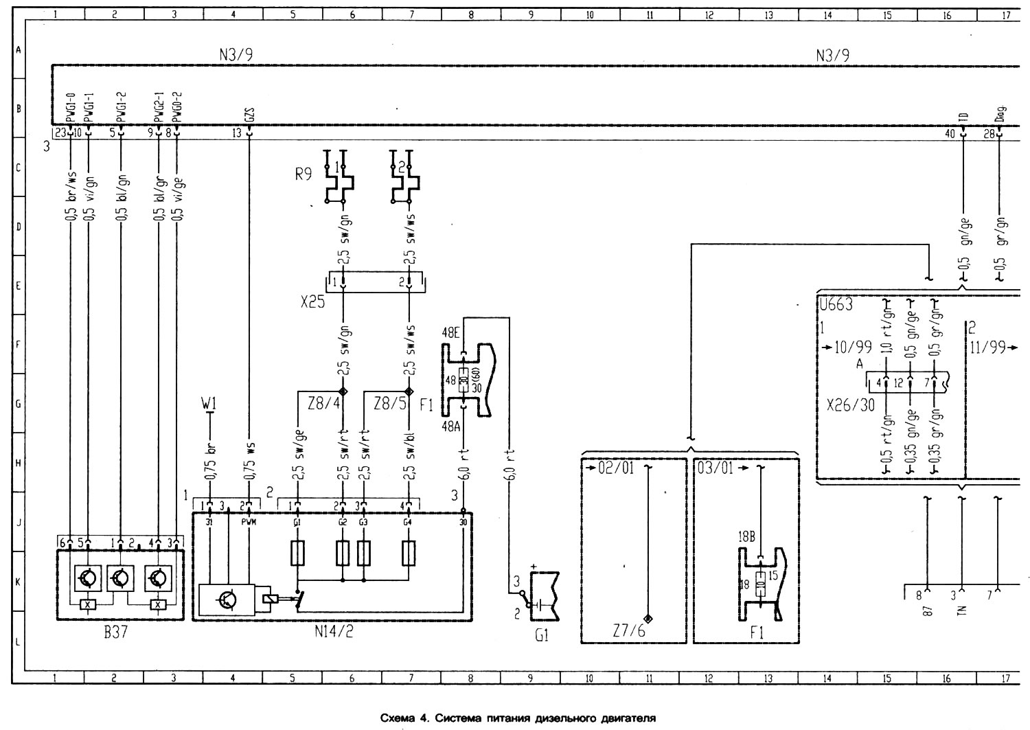
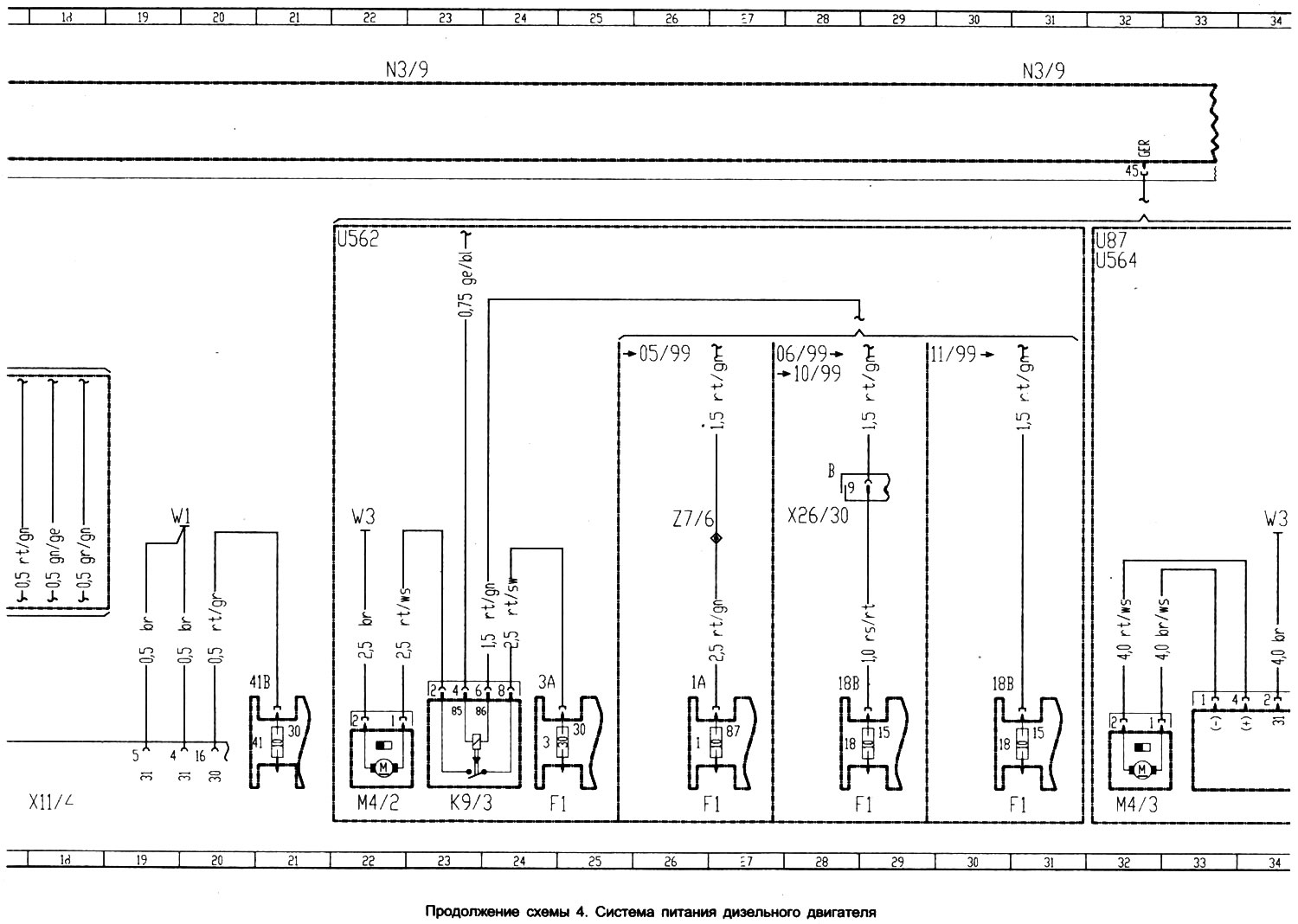
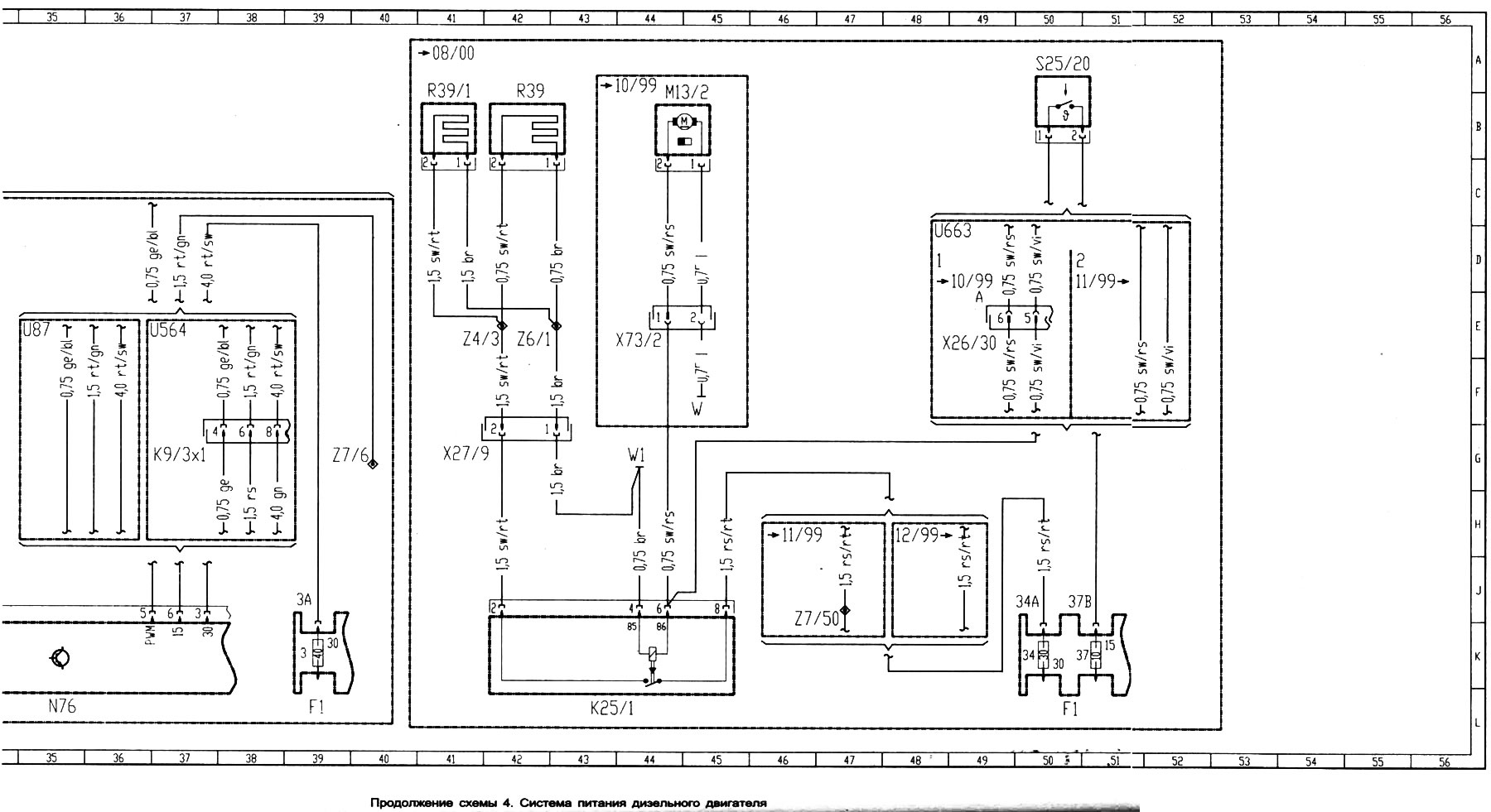
Scheme 4. Fuel system of a diesel engine
Open a larger image in a new tab »
Open a larger image in a new tab »
Open a larger image in a new tab »
- B37 accelerator pedal position sensor
- F1 fuse and relay box
- Fn1 fuse 1
- Fn3 fuse 3
- Fn18 fuse 18
- Fn34 fuse 34
- Fn37 fuse 37
- Fn41 fuse 41
- Fn48 fuse 48
- G1 battery
- K9/3 relay of electric radiator fan
- K9/Zx1 air conditioner plug
- K25/1 water pump relay
- M4/2 radiator fan electric motor
- M4/3 electric fan
- M1 3/2 heater
- N3/9 Diesel Engine Power Control Unit
- N76 Radiator Fan Control Relay
- R9 glow plugs
- R39 heater
- R39/1 Fan heating element
- S25/20 Boost Air Temperature Sensor
- S9/1 brake light switch
- U87 for air conditioner
- U562 for heater
- U65 for restraint system without side airbags
- U5 64 for air conditioner
- W1 ground point (-) under the control unit
- W3 point of "mass" (-) on the left wing
- X11/4 diagnostic connector
- X25 diagnostic connector plug
- Z6/20 Engine Compartment/Instrument Panel Wiring Harness Connection
- Z27/9 water pump plug
- Z73/2 water pump plug
- Z4/3 terminal 30
- Z6/1 point "mass" (-)
- Z7/6 terminal 87
- Z7/50 terminal 30 from fuse Fn34
- Z8/4 plug for preheating spark plugs of cylinders 1 and 2
- Z8/5 plug for preheating spark plugs of cylinders 3 and 4
[Original source of information mercedesman]